Communication System Manual 3WN1, 3WS1 Circuit-Breakers
82 Copyright Siemens AG 1998. All rights reserved. Version 1.0 (08/98)
4.3 Procedure for connection to communication system
3WN1/3WS1 circuit-breakers are connected to PROFIBUS-DP in 8 steps:
56
Step 1: Check that all the system components are fitted
Step 2: Check the system requirements
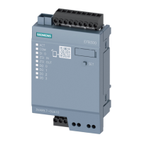
Step 3: Connect the I/O module
Step 4: Connect 3RK1002 interface module to PROFIBUS-DP
Step 5: Connect 3RK1002 interface module to 3WN1/3WS1
Step 6: Connect 3RK1002 interface module to voltage supply
Step 7: Bus configuration
Step 8: Set bus address on 3RK1002 interface module
Step 1: Check that all the system components are fitted
Check that all the following system components are fitted before connecting 3WN1/3WS1 to
PROFIBUS-DP:
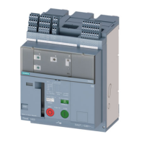
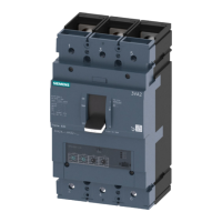
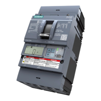
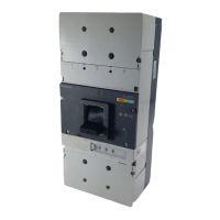
• Communication-capable 3WN1/3WS1 circuit-breaker
• 3RK1002 interface module and connecting cable from 3RK1002 interface module to circuit-
breaker (supplied with 3RK1002)
• Connector (6ES7xxx) including terminating resistor for connecting interface module to
PROFIBUS-DP
• 24 V DC voltage supply (DIN 19240)
• Diskette with type or GSD file (supplied with 3RK1002)
• I/O module (e.g. ET 200 U)
• Programming device PG ... (for SIMATIC S5/S7, or other appropriate hardware)
• COM ET 200 software/COM-PROFIBUS (for SIMATIC S5, or other appropriate software)
56)
This procedure must be performed for each individual 3WN1 circuit-breaker.

 Loading...