Communication System Manual 3VF Circuit-Breakers
Copyright Siemens AG 1998. All rights reserved. Version1.0 (05/98)
10
2.1.3 Hardware and software connections of 3VF
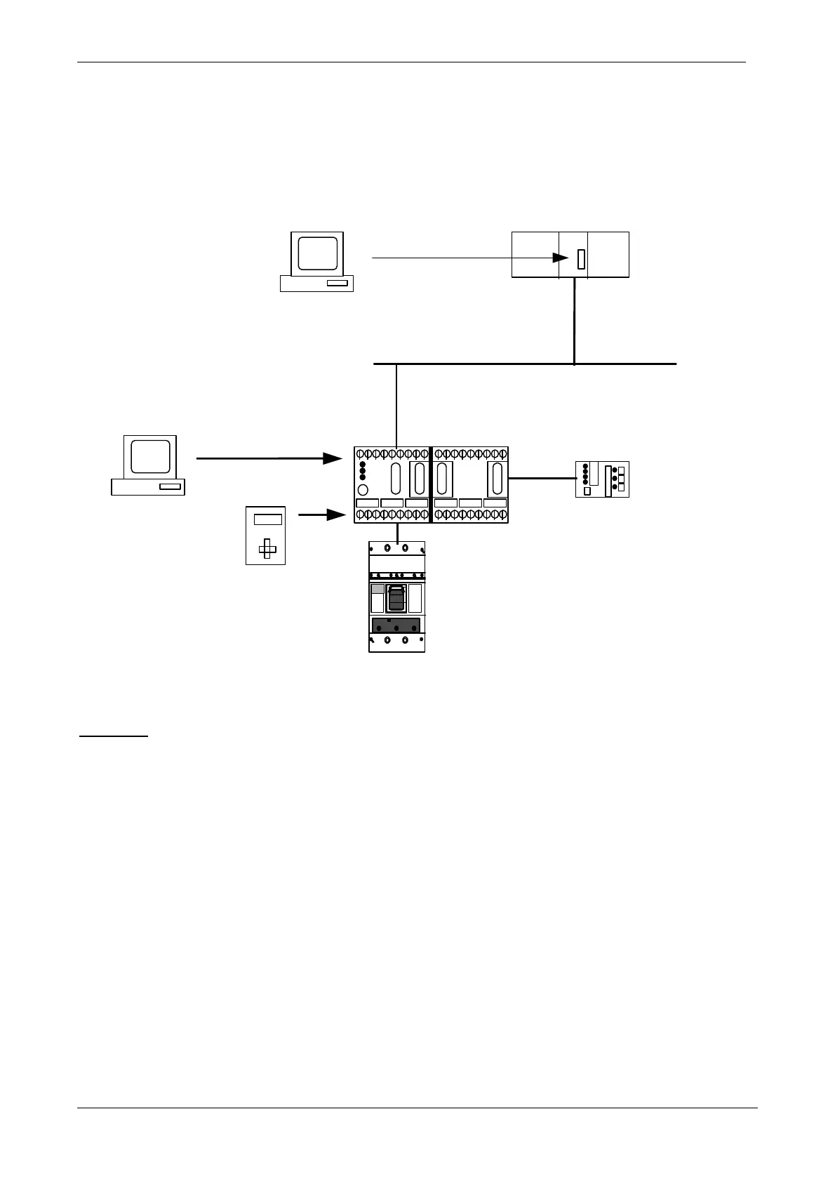
Fig. 2: Possible system components
Hardware:
1.) PC or programming device (PG) for offline parameterization of master and slave-specific data via
COM-PROFIBUS
Two configuring modes are possible via COM-PROFIBUS:
a) Bus configuration: type or GSD files, control data (always 4 bytes in length)
b) Parameterization: set device-specific parameters
2.) PROFIBUS-DP MASTER e.g. IM308C for SIMATIC S5
3.) PC or notebook for SIMOCODE-DP parameterization and for operation and monitoring
(Win-SIMOCODE-DP software is required, see software)
4.) Handheld operator panel (order no. 3WX3647-6JA00) for parameterization, operation and monitoring
of SIMOCODE-DP; functionality includes: baud rate setting, slave address, base type.
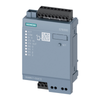
5.) SIMOCODE-DP basic unit (cf. Selection and ordering data, page 17)
PROFIBUS-DP
COM-PROFIBUS
SPS
3UF50 3UF51
3UF52
1.)
2.)
PC/PG
IM
308 C
PC
ON
2
LO
HI
6
7
5
3
4
2
LO
HI
6
7
5
3
4
2
LO
HI
6
7
5
3
4
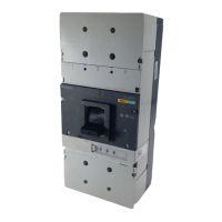
3VF...
3.)
4.)
5.)
6. )
7.)
8.)
WIN-SIMOCODE DP
PG
(Host + Master)

 Loading...