28
Siemens · 10/2014
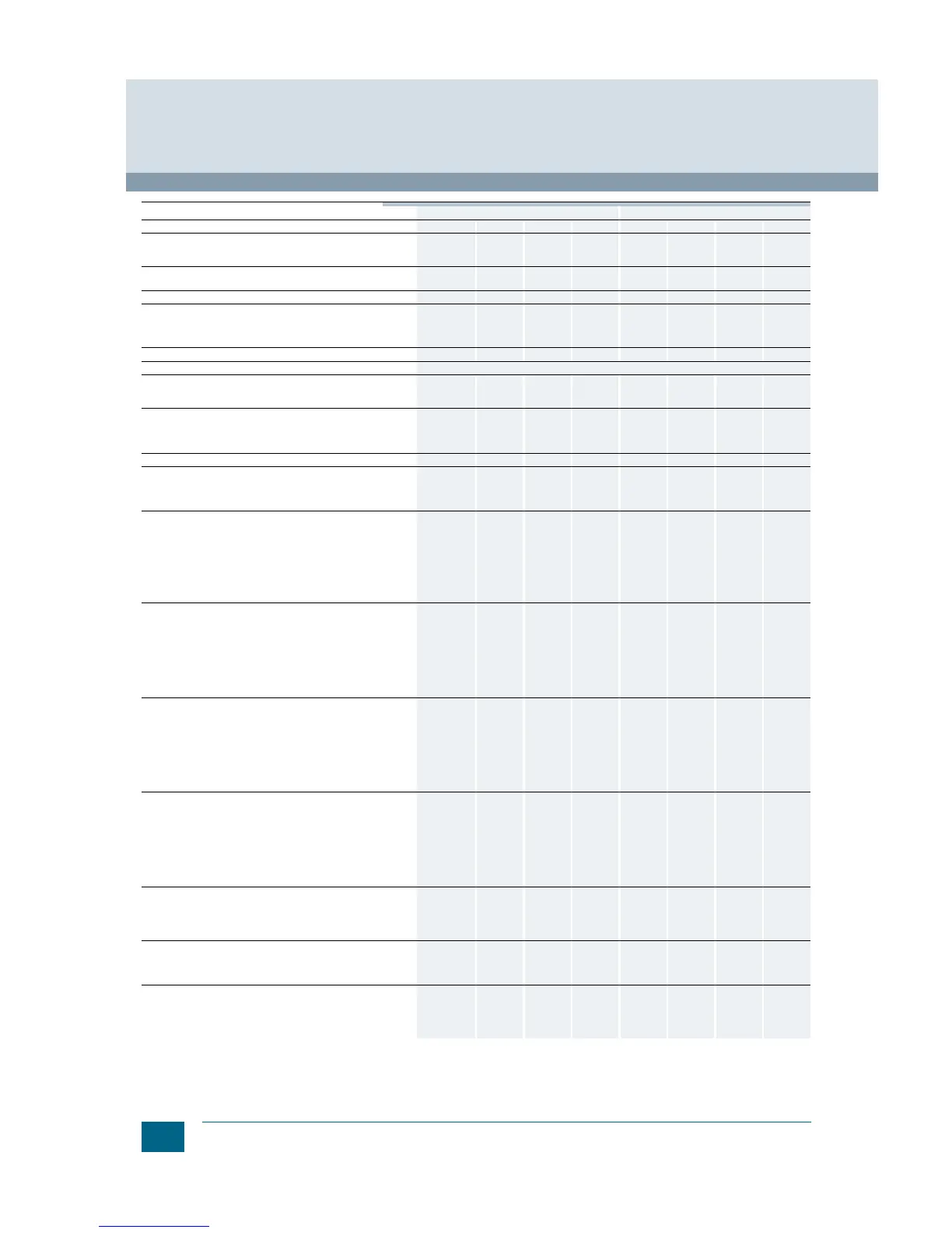
General data
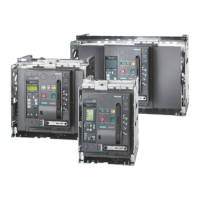
3WL Air Circuit Breakers
3WL air circuit breakers/non-automatic air circuit breakers up to 6300 A (AC), IEC
1)
Use of trip units from –20 °C.
2)
ETU76B with graphics display can be used up to max. 55 °C.
3)
At breaking capacity H: 1600 A to 70 °C.
4)
Make-time through closing solenoid for synchronization purposes
(short-time excited) 50 ms.
5)
Maintenance means: replace main contact elements and arc chutes
(see Operating Manual).
6)
Replacement of the main contact elements of circuit breakers size I
with breaking capacity H is only possible at the factory.
7)
Minimum interval time between 2 tripping operations.
8)
3-pole switching with breaking capacity N and S: 45/h.
Size I II
Type ... 3WL11 10 3WL11 12 3WL11 16 3WL11 20 3WL12 08 3WL12 10 3WL12 12 3WL12 16
Rated current I
n
at 40 °C, at 50/60 Hz
Main conductor
N conductor (only on 4-pole versions)
A
A
... 1000
... 1000
1250
1250
1600
1600
2000
2000
800
800
1000
1000
1250
1250
1600
1600
Rated operational voltage U
e
at 50/60 Hz
(1000 V version, see Catalog LV 10, "Options")
V AC ...
690/1000
...
690/1000
...
690/1000
...
690/1000
...
690/1000
...
690/1000
...
690/1000
...
690/1000
Rated insulation voltage U
i
V AC 1000 1000 1000 1000 1000 1000 1000 1000
Rated impulse withstand voltage U
imp
• Main conducting paths
• Auxiliary circuits
• Control circuits
kV
kV
kV
12
4
2.5
12
4
2.5
12
4
2.5
12
4
2.5
12
4
2.5
12
4
2.5
12
4
2.5
12
4
2.5
Isolating function acc. to EN 60947-2
Yes Yes Yes Yes Yes Yes Yes Yes
Utilization category
B
Permissible ambient temperature
• During operation (in operation with LCD max. 55 °C)
1)
•Storage
C
C
–25/+70
–40/+70
–25/+70
–40/+70
–25/+70
–40/+70
–25/+70
–40/+70
–25/+70
–40/+70
–25/+70
–40/+70
–25/+70
–40/+70
–25/+70
–40/+70
Permissible load for
withdrawable versions
At rear horizontal main
connections
•Up to 55 C (Cu bare)
•Up to 60 C (Cu bare)
2)
•Up to 70 C
(Cu black painted)
2)
A
A
A
1000
1000
1000
1250
1250
1210
1600
1600
1490
3)
2000
1930
1780
800
800
800
1000
1000
1000
1250
1250
1250
1600
1600
1600
Rated rotor operational voltage U
er
V 2000 2000 2000 2000 2000 2000 2000 2000
Power loss at I
n
With 3-phase symmetrical load
• Fixed-mounted circuit breakers
• Withdrawable circuit breakers
W
W
100
195
105
205
150
350
240
440
40
85
45
95
80
165
85
175
Switching times
• Make time
• Opening time
• Electrical make time (through closing solenoid)
4)
• Electrical opening time (through shunt release)
• Electrical opening time (instant. undervoltage release)
• Opening time due to ETU, instantaneous short-circuit
release
ms
ms
ms
ms
ms
ms
35
38
80
73
73
50
35
38
80
73
73
50
35
38
80
73
73
50
35
38
80
73
73
50
35
34
100
73
73
50
35
34
100
73
73
50
35
34
100
73
73
50
35
34
100
73
73
50
Service life: Breaking capacity N and S, 3-/4-pole
• Mechanical (without maintenance) Operating cycles
• Mechanical (with maintenance)
5)
Operating cycles
• Electrical (without maintenance) Operating cycles
• 1000 V version, electrical
(without maintenance) Operating cycles
• 1150 V version, electrical
(without maintenance) Operating cycles
• Electrical (with maintenance)
5)
Operating cycles
10 000
20 000
10 000
--
--
20 000
10 000
20 000
10 000
--
--
20 000
10 000
20 000
10 000
--
--
20 000
10 000
15 000
7500
1000
--
15 000
10 000
15 000
7500
1000
500
15 000
10 000
15 000
7500
1000
500
15 000
10 000
15 000
7500
1000
500
15 000
10 000
15 000
7500
1000
500
15 000
Service life: Breaking capacity H, 3-pole
• Mechanical (without maintenance) Operating cycles
• Mechanical (with maintenance)
5)
Operating cycles
• Electrical (without maintenance) Operating cycles
• 1000 V version, electrical
(without maintenance) Operating cycles
• 1150 V version, electrical
(without maintenance) Operating cycles
• Electrical (with maintenance)
5)6)
Operating cycles
10 000
15 000
7 500
1000
--
15 000
10 000
15 000
7500
1000
--
15 000
10 000
15 000
7 500
1000
--
15 000
10 000
15 000
7500
1000
--
15 000
10 000
15 000
7500
1000
500
15 000
10 000
15 000
7500
1000
500
15 000
10 000
15 000
7500
1000
500
15 000
10 000
15 000
7500
1000
500
15 000
Service life: Breaking capacity H, 4-pole
• Mechanical (without maintenance) Operating cycles
• Mechanical (with maintenance)
5)
Operating cycles
• Electrical (without maintenance) Operating cycles
• 1000 V version, electrical
(without maintenance) Operating cycles
• 1150 V version, electrical
(without maintenance) Operating cycles
• Electrical (with maintenance)
5)6)
Operating cycles
10 000
15 000
7 500
1000
--
10 000
10 000
15 000
7500
1000
--
10 000
10 000
15 000
7 500
1000
--
10 000
10 000
15 000
7500
1000
--
10 000
10 000
15 000
7500
1000
500
15 000
10 000
15 000
7500
1000
500
15 000
10 000
15 000
7500
1000
500
15 000
10 000
15 000
7500
1000
500
15 000
Service life: Breaking capacity C
• Mechanical (without maintenance) Operating cycles
• Mechanical (with maintenance)
5)
Operating cycles
• Electrical (without maintenance) Operating cycles
• Electrical (with maintenance)
5)
Operating cycles
--
--
--
--
--
--
--
--
--
--
--
--
--
--
--
--
5 000
10 000
5 000
10 000
5 000
10 000
5 000
10 000
5000
10 000
5000
10 000
5 000
10 000
5 000
10 000
Switching frequency
7)
• 690 V version
• 1000 V version
• 1150 V version
1/h
1/h
1/h
60
8)
--
--
60
8)
--
--
60
8)
--
--
60
20
--
60
8)
20
20
60
8)
20
20
60
8)
20
20
60
8)
20
20
Minimum interval between tripping operation by
electronic trip unit and next making operation of the
circuit breaker (only with autom. mechanical resetting
of the lockout device).Minimum interval between On-Off
or Off-On switching operations.
ms
80 80 80 80 80 80 80 80
© Siemens AG 2015
 Loading...