29
Siemens · 10/2014
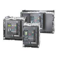
3WL Air Circuit Breakers
3WL air circuit breakers/non-automatic air circuit breakers up to 6300 A (AC), IEC
General data
Size I II
Type ... 3WL11 10 3WL11 12 3WL11 16 3WL11 20 3WL12 08 3WL12 10 3WL12 12 3WL12 16
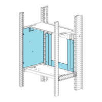
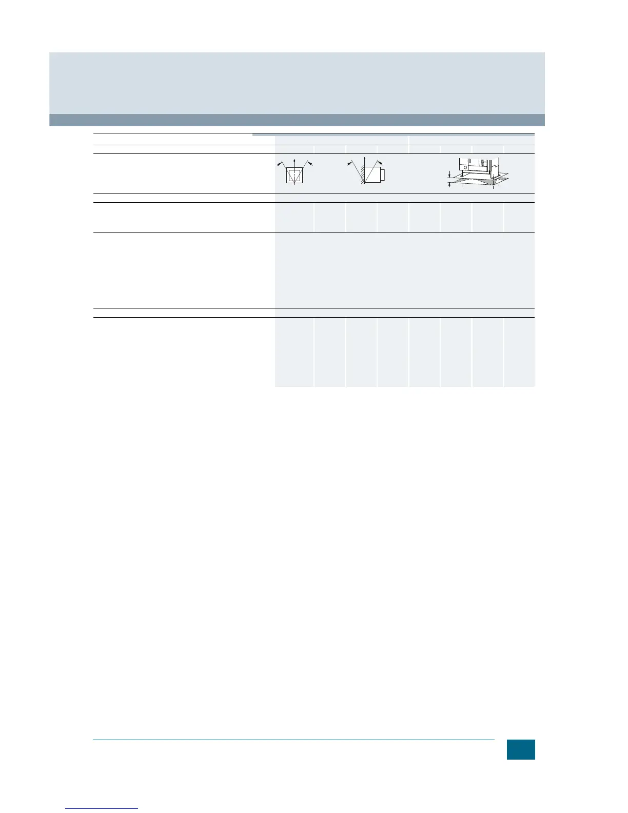
Mounting position
and/
or
Degree of protection IP20 without cabinet door, IP41 with door sealing frame, IP55 with cover
Main conductor
minimum
cross-sections
• Copper bars,
bare
• Copper bars,
painted black
Unit(s)
mm
2
Unit(s)
mm
2
1 ×
60 × 10
1 ×
60 × 10
2 ×
40 × 10
2 ×
40 × 10
2 ×
50 × 10
2 ×
50 × 10
3 ×
50 × 10
3 ×
50 × 10
1 ×
50 × 10
1 ×
50 × 10
1 ×
60 × 10
1 ×
60 × 10
2 ×
40 × 10
2 ×
40 × 10
2 ×
50 × 10
2 ×
50 × 10
Auxiliary conductors (Cu)
Max. number
Auxiliary conductors ×
cross-section
(solid/stranded)
Standard connection =
strain-relief clamp
• Without end sleeve
• With end sleeve acc. to
DIN 46228 Part 2
• With twin end sleeve
2 × 0.5 mm
2
(AWG 20) ... 2 × 1.5 mm
2
(AWG 16); 1 × 2.5 mm
2
(AWG 14)
1 × 0.5 mm
2
(AWG 20) ... 1 × 1.5 mm
2
(AWG 16)
2 × 0.5 mm
2
(AWG 20) ... 2 × 1.5 mm
2
(AWG 16)
Optional connection =
tension spring
• Without end sleeve
• With end sleeve acc. to
DIN 46228 Part 2
2 × 0.5 mm
2
(AWG 20) ... 2 × 2.5 mm
2
(AWG 14)
2 × 0.5 mm
2
(AWG 20) ... 2 × 1.5 mm
2
(AWG 16)
Position signaling switches Tension spring terminals
1 × 0.5 mm
2
(AWG 20) ... 1 × 2.5 mm
2
(AWG 14)
Weights 3-pole
4-pole
• Fixed-mounted circuit
breakers
• Withdrawable circuit
breakers
• Guide frames
• Fixed-mounted circuit
breakers
• Withdrawable circuit
breakers
• Guide frames
kg
kg
kg
kg
kg
kg
43
45
25
50
54
30
43
45
25
50
54
30
43
45
25
50
54
30
43
45
25
50
54
30
56
60
31
67
72
37
56
60
31
67
72
37
56
60
31
67
72
37
56
60
31
67
72
37
NSE0_00061a
30°
30°