50
Siemens · 10/2014
Project planning aids
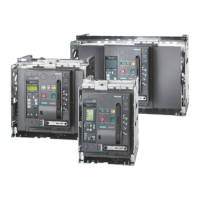
3WL Air Circuit Breakers
3WL air circuit breakers/non-automatic air circuit breakers up to 6300 A (AC), IEC
■
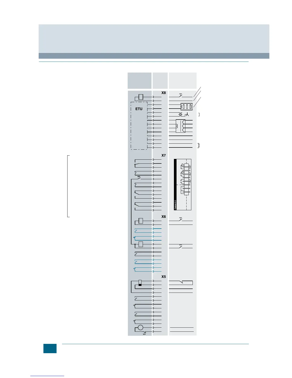
Circuit diagrams
Terminal assignment diagram
Internal wiring
24 V DC input
Remote reset bell alarm & tripped indicator
G transformer
N sensor
N sensor
ext. voltage transformer Com
ext. voltage transformer
ext. voltage transformer
ext. voltage transformer
0 V DC
24 V DC
G transformer
"Spring charged" signal
1st auxiliary release F1 "ST"
S1 "NO"
S1 "NC"
Closing solenoid
"Ready to close" signal
S2 "NO"
S2 "NC"
F4 only "quick OFF"
F4 only "quick OFF"
2nd auxiliary release: F2 "ST", F3 "UVR", F4 "UVR td"
S3 "NO" or S7 "NO"
S3 "NC" or S7 "NO"
S4 "NO" or S8 "NO"
S4 "NC" or S8 "NO"
EMERGENCY STOP
or short terminals
Terminals External wiring
Short terminals if no N-sensor
Electric CLOSE
opt. motor main switch
Charging motor
(Option F02/F12)
e.g. current transformer in the
star point of power transformer
or a summation current
transformer 1200 A /1A
1st trip signalling switch
(position after tripping)
2nd trip signalling switch S25 1NO
Signaling contact at the
2nd auxiliary release
Termination resistor,
if not external CB module!
Not available with communication connection "F02" or "F12".
COM15/COM16 module is at position "-X7".
optional
Accessories
(Auxiliary switch S1, S2 = Standard)
Signaling contact at the
1st auxiliary release
NSE0_00605q
L1
L2
L3
N
14
13
12
11
10
9
8
7
6
5
4
3
2
1
14
13
12
11
10
9
8
7
6
5
4
3
2
1
14
13
12
11
10
9
8
7
6
5
4
3
2
1
L / L+
U
s
/U
c
U
s
/U
c
U
c
U
c
U
c
U
c
N / L–
L / L+
N / L–
N / L–
L / L+
L / L+
N / L–
L / L+
L / L+
14
13
12
11
10
9
8
7
6
5
4
3
2
1
N / L–
M
123456789
DPWrite
Enable
Free Free Close Open
+
–
+
–
+
–
IN OUT
External
Internal
Y1
F1, 2
(sw) (br)
CubicleBUS +
CubicleBUS –
COM15/COM16
F7
S2
S1
S2
S1
S24
S21
S10
S22
S23
S20
S12
L3
L2
L1