51
Siemens · 10/2014
3WL Air Circuit Breakers
3WL air circuit breakers/non-automatic air circuit breakers up to 6300 A (AC), IEC
Project planning aids
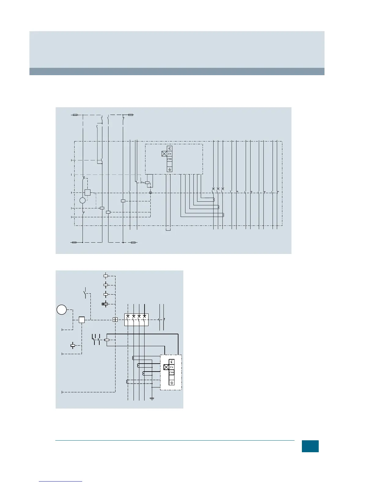
Example of an overall circuit diagram for 3WL circuit breakers
(3WL1. ..–.....–4GN4–Z C11+ C22 + K07)
Manual / motorized operating mechanism with stored-energy
feature, with electric ON button (option C11), with ready-to-close
signaling switch (option C22), with electronic trip unit LSING with
undervoltage release"UVR" (F3), with shunt trip "ST" (F1), with trip
alarm switch (option K07), with auxiliary switch 4 NO + 4 NC.
Function diagram of 3WL air circuit breaker
-A1 ETU electronic trip unit
-S1/-S2 1st auxiliary switch block (2 NO + 2 NC)
-S3/-S4 2nd auxiliary switch block (2 NO + 2 NC)
-S7 (optional) 2nd auxiliary switch block, S7 (2 NO) can be used
if there is no S3 – S3 and S7 have
the same terminal assignment/mounting location
-S8 (optional) 2nd auxiliary switch block, S8 (2 NO) can be used
if there is no S4 – S4 and S8 have
the same terminal assignment/mounting location
3WL1. ..-.....-...2 (2 NO + 2 NC) S1+S2
3WL1. ..-.....-...4 (4 NO + 4 NC) S1+S2+S3+S4
3WL1. ..-.....-...7 (6 NO+ 2 NC) S1+S2+S7+S8
3WL1. ..-.....-...8 (5 NO + 3 NC) S1+S2+S3+S8
-S10 Electrical ON button
-S11 Internal motor shutdown switch (if spring is tensioned)
-S12 Motor shutdown switch
(no automatic tensioning of spring)
-S20 Ready-to-close signaling switch
-S24 Trip alarm switch
-F1 1st auxiliary release shunt release
-F3 2nd auxiliary release undervoltage release
-F5 Tripping solenoid
-M Motor for "charging energy store"
-P Stored-energy mechanism
-QS Actuator lever for "charging energy store"
-Q1 Main contacts
-T1/-T2/-T3 Current transformers
-X5/-X6/-X7/-X8 Terminals
-Y1 Closing solenoid
-R Display and reset button for electronic trip unit
-X8.9/-X8.10 Connection option: external N transformer