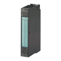
Do you have a question about the Siemens 6ES7151-1AA06-0AB0 and is the answer not in the manual?
Shows the terminal connections for the interface module for voltage supply and PROFIBUS DP.
Provides detailed technical data, dimensions, weight, and module-specific information.
Lists and describes the configurable parameters for the IM151-1 STANDARD interface module.
Provides a detailed explanation of each parameter, its function, and settings.
Explains the principle and usage of RESERVE modules for flexible configuration of the ET 200S.
Details the principle and configuration of option handling when RESERVE modules are not used.
Illustrates and explains the meaning of the LEDs (SF, BF, ON) on the interface module for status indication.
Explains how diagnostic messages are handled and reported in DPV0 and DPV1 modes.
Details methods for reading out slave diagnostics using STEP 7, including SFCs and data structures.
Explains how identifier-related diagnostics indicate errors or faults in ET 200S modules.
Provides information about channel errors and details from identifier-related diagnostics.
Identifies invalid module configuration states that cause station failure or prevent data exchange.
Guides on how to interpret and handle diagnostic, process, and remove/insert module interrupts.
Explains how to calculate the ET 200S response time using a provided formula and example.
| Firmware version | V2.0 |
|---|---|
| Engineering with | TIA Portal |
| Rated Value (DC) | 24 V |
| Permissible range, lower limit (DC) | 20.4 V |
| Permissible range, upper limit (DC) | 28.8 V |
| Number of Digital Inputs | 16 |
| Number of Digital Outputs | 0 |
| Number of Analog Inputs | 0 |
| Number of Analog Outputs | 0 |
| Number of Encoders | 0 |
| Number of Channels per Encoder | 0 |
| Number of Ports | 2 |
| Integrated Switch | Yes |
| Web Server | Yes |
| Input Voltage | 24 V DC |
| CPU Type | CPU 151-1 |
| Module Class | CPU |
| Type of Connection | PROFINET, PROFIBUS |
| Number of Alarm Inputs | 0 |
| Operating Temperature | 0 °C to 60 °C |


 Loading...