Connection
5.1 Line and motor connection
PM250 Power Module
36 Hardware Installation Manual, 01/2016, A5E36265179B-AA
Table 5- 3 Connection type, cable cross sections and tightening torques
Cross-section and tightening torque
Line cable, motor cable
and braking resistor
Terminal 4 …10 mm: 2.3 Nm 12 … 8 AWG: 20 lbf in 10 mm
Line cable, motor cable
Cable
10 … 35 mm
2
: 6 Nm 7 … 2 AWG: 53 lbf in --
Line cable, motor cable
Cable
25 … 35 mm
2
: 6 Nm 3 … 2 AWG: 53 lbf in
--
Line cable, motor cable
Cable
35 … 120 mm
2
: 13 Nm 2 … 4/0 AWG: 115 lbf in
--
-sections specified refer to possible cable cross-sections for the terminals, not for the current that you require for
your particular application.
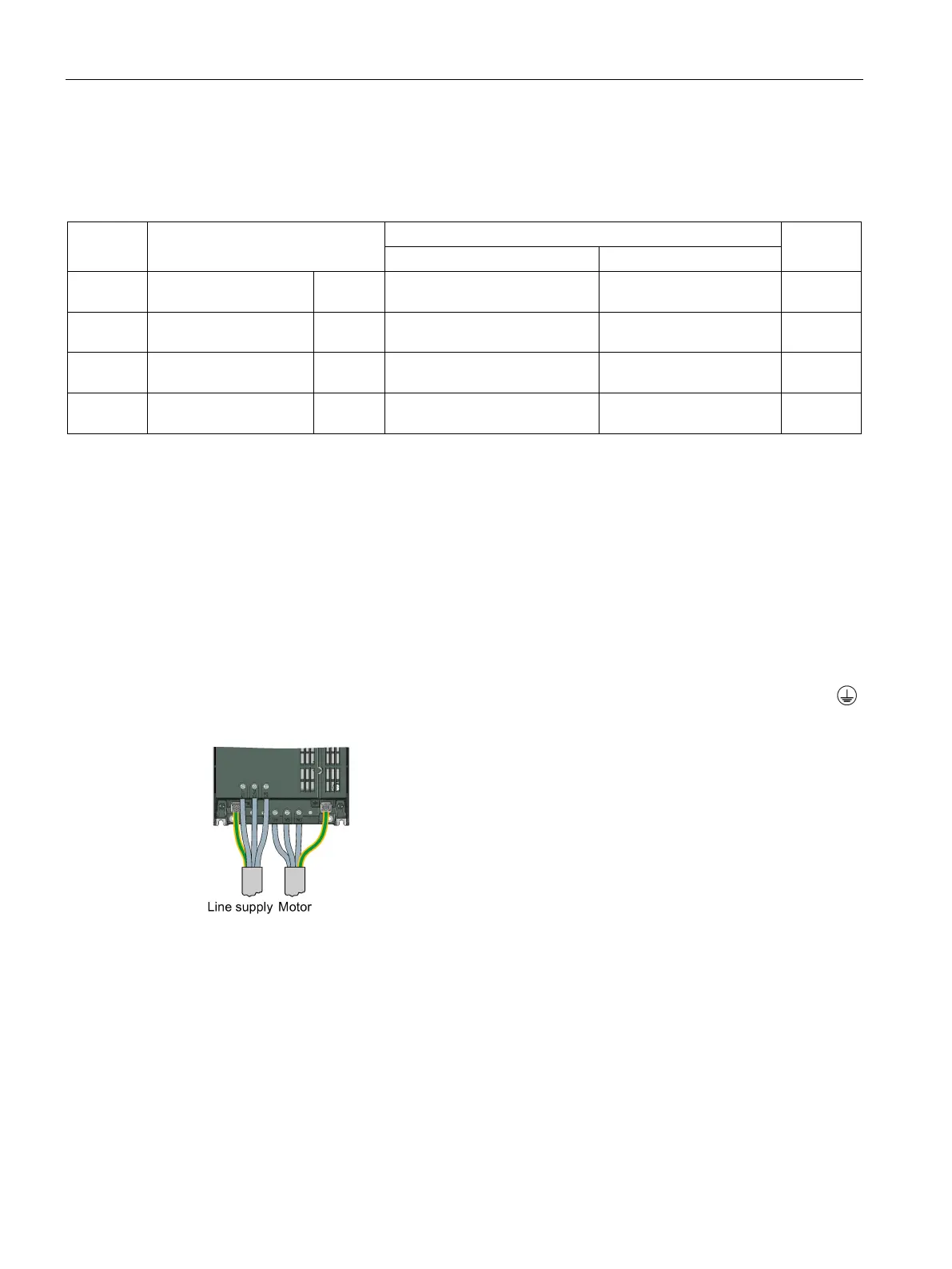
Establishing connections
Establishing the line and motor connection, frame size FSA
The terminals are directly accessible.
Connect the line cable phases to terminals L1, L2, L3 and the protective conductor to PE.
Connect the motor cable phases to terminals U2, V2, W2 and the protective conductor to
.
 Loading...
