EasyManua.ls Logo

Siemens 7VE51 User Manual

Siemens 7VE51
104 pages
To Next Page IconTo Next Page
Page #1 background imageLoading...
Page #1 background image
6% 6
.UMERICAL 0ARALLELING $EVICE
)NSTRUCTION -ANUAL
/RDER .O #
' #
&IGURE )LLUSTRATION OF THE NUMERICAL PARALLELING DEVICE 6% IN FLUSH MOUNTING CASE
D 3IEMENS !' 
Question and Answer IconNeed help?

Do you have a question about the Siemens 7VE51 and is the answer not in the manual?

Siemens 7VE51 Specifications

General IconGeneral
Communication protocolsModbus
Protection functionsOvercurrent
Breaking CapacityN/A (Protection Relay)
PolesN/A (Protection Relay)
Trip UnitN/A (Protection Relay)

Summary

Conformity

Introduction

Application

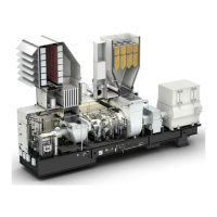
Details the device's suitability for paralleling generators and synchronous voltage sources.

Features

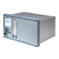
Outlines the key capabilities and components of the paralleling device.

Design

Arrangements

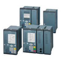
Details the different housing types and their arrangements.

7VE511 Housing Dimensions (Surface Mounting)

7VE511 Housing Dimensions (Flush Mounting)

7VE512 Housing Dimensions (Surface Mounting)

7VE512 Housing Dimensions (Flush Mounting)

Ordering Data

Technical Data

General Data

Covers basic electrical specifications, inputs, outputs, and environmental conditions.

Inputs/Outputs

Details electrical characteristics of input and output circuits.

Electrical Tests

Mechanical Stress Tests

Climatic Stress Tests

Service Conditions

Design

Paralleling

Setting Ranges/Steps

Defines operating ranges and step sizes for paralleling parameters.

Tolerances

Specifies acceptable deviations for voltage, frequency, and angle.

Frequency and Voltage Balancing

Setting Ranges/Steps

Sets ranges for frequency and voltage balancing parameters.

Ancillary Functions

Method of Operation

Operation of Complete Unit

Explains the overall operation and hardware structure of the device.

Paralleling of Generators with Systems

Automatic Synchronizing of Generators

Output of Status Signals

Measurement Sequence

Ancillary Functions

Processing of Annunciations

Explains how annunciations are processed and displayed.

Routine Operational Measurements

Details how to perform and interpret routine operational measurements.

Monitoring Functions

Covers hardware and software monitoring capabilities.

Installation Instructions

Unpacking and Repacking

Provides guidance on safely unpacking the device.

Preparations

Covers essential steps before installation.

Mounting and Connections

Checking the Rated Data

Connections

Checking the Connections

Operating Instructions

Safety Precautions

Highlights critical safety measures for operating the device.

Dialog with the Device

Explains how to interact with the device via its interface and PC.

Operation with a Personal Computer

Operational Preconditions

Membrane Keyboard and Display Panel

Representation of the 7VE51 (Front Views)

Setting the Operational Parameters

Introduction

Introduces the process of setting operational parameters.

Initial Displays – Address Blocks 00 and 10

Power System Data – Address Block 11

General Information on Parameter Blocks

Settings for Function Range

Settings for Paralleling

Settings for Frequency Balancing

Settings for Voltage Balancing

Settings for Frequency Balancing (Continued)

Settings for Frequency Balancing (Continued)

Settings for Voltage Balancing

Output of Status Signals

Annunciations

Introduction

Introduces the annunciations and their purpose.

Operational Annunciations on Display/Interface

Annunciations Concerning Paralleling Procedure

Annunciations on LED Indicators and Output Signals

Read-out of Operational Measured Values

Commissioning

General

Outlines the general requirements for commissioning the device.

Checking the Control Circuits

Details procedures for checking the control circuits before operation.

Checking the Measured Voltage Circuits

Measuring Circuit Breaker Closing Time

Dummy Synchronization Attempts

Paralleling Procedure

Paralleling of Synchronous Systems

Details the process for paralleling synchronous systems.

Paralleling of Asynchronous Systems

Synchronization of Generators

Reactions to Faults during Paralleling

Maintenance and Fault Tracing

Routine Checks

Specifies routine checks for maintaining device performance.

Fault Tracing

Provides methods for identifying and diagnosing faults within the device.

Replacing the Mini-Fuse

Repairs

Storage

Appendix

General Diagrams

Presents overall schematic diagrams of the device's electrical connections.

Connection Diagrams

Shows detailed connection examples for different device configurations.

Tables

Lists reference tables for binary inputs, outputs, and functional parameters.

Related product manuals