Do you have a question about the Siemens sitrans and is the answer not in the manual?
Explains safety alert symbols and danger grading for notices.
Defines personnel qualified to operate the product/system based on training and experience.
Notes on using Siemens products safely, including transport, storage, and installation.
Identifies registered trademarks of Siemens AG and other third-party trademarks.
States limitations on publication consistency and guarantees, and the need for regular review.
To familiarize users with steps to prevent EMC interference between VFDs and instrumentation.
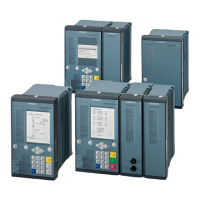
Lists the VFD drive and Process Instrumentation equipment covered.
States no warranty of accuracy or usability is expressed or implied for the information provided.
Defines Variable Frequency Drives (VFDs) and their function in controlling AC motor speed.
Explains the VFD system's components: drive converter, AC motor, and control interface.
Provides recommendations for installation to prevent EMC interference from VFDs.
Covers EMC standards like EN/IEC 61800-3 in Europe and FCC CFR Title 47 in the US.
This application guide describes the function of Variable Frequency Drives (VFDs) and provides tips on how to prevent interference issues when VFDs are used with process instrumentation. The objective of this application guide is to help the user become familiar with the steps required to prevent EMC interference between VFDs and instrumentation.
A Variable Frequency Drive or VFD controls the rotation of an alternating current motor by varying the frequency of the electrical power supplied to the motor. These flexible systems provide accurate speed control and minimize energy usage by matching motor output to a required load. For example, rather than using a fixed speed motor for a fan or pump and inefficiently controlling flow output through a damper or valve, the motor speed can be varied to directly control the rate of flow. VFDs also have soft start capabilities that reduce peak current draws and wear on electrical and mechanical parts. These devices are also known as Variable Speed Drives, Adjustable Frequency Drives, or Inverter Drives.
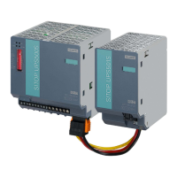
A 'drive' refers specifically to the voltage and frequency converter that controls the output to the motor. A complete system generally includes a drive converter, an AC motor, and a configuration and control interface. The drive converter takes an Alternating Current (AC) input and rectifies it to Direct Current (DC). This intermediate DC voltage is changed again to AC at a desired frequency and amplitude using a switching inverter stage. This voltage is output to a motor and the frequency and amplitude varied by a microcontroller to control speed. The motor is typically a three-phase induction motor, although other configurations are possible. The configuration and control interface for the VFD system can be a Human Machine Interface (HMI), a setpoint input or a module for interfacing to a communications bus, such as PROFIBUS DP.
The operating function of VFDs causes electromagnetic noise. The high-speed switching of the inverter stage can emit significant radio frequency energy. Without mitigation, this energy can interfere with other nearby electrical equipment. Process control and sensor instrumentation is often found in the same area of a factory or process as VFDs. Some of this equipment can be sensitive to interference from electromagnetic sources and this can cause performance degradation ranging from incorrect measurements to disabled instruments. Precise and reliable measurements require careful installation and configuration.
Some general installation recommendations will apply in all cases where instrumentation and VFDs are mounted near each other:
The specifics of electromagnetic compatibility and standards are beyond the scope of this document, but an overview is provided. Contact the drive manufacturer for specific details and regional requirements. In Europe, VFDs are covered under EMC product standard EN or IEC 61800-3 for Power Drive Systems. This standard covers the complete system including drive, interface, motor, and cables. In the United States, VFD systems are covered in a general manner by FCC CFR Title 47, Part 15, but there are no specific product requirements or test procedures. The manufacturer of the drive is not responsible for guaranteeing the EMC performance of the fully installed drive and motor, but they will provide information on the EMC characteristics, use, and installation of the device as part of a drive system. Generally, the manufacturer can also supply optional filters and other equipment that will improve EMC performance.
| Category | Industrial Equipment |
|---|---|
| Type | Process Instrumentation |
| Manufacturer | Siemens |
| Product Family | SITRANS |
| Types | Flow, Level, Pressure, Temperature |
| Communication Protocols | HART, PROFIBUS PA, Foundation Fieldbus, Modbus |
| Operating Temperature | -40°C to +85°C (varies by model) |
| Protection Class | IP65, IP67, IP68 |