P/N 315-049708-5
Siemens Industry, Inc.
Building Technologies Division
10
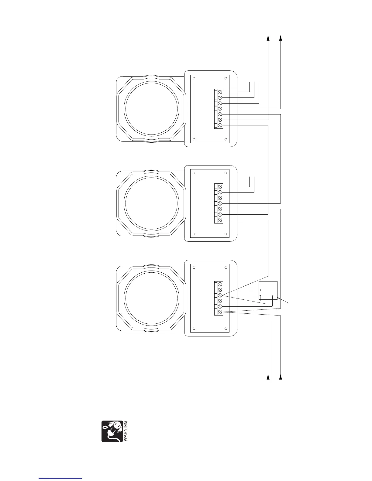
Figure 7
Typical Connections for the AD2-P / AD2-XHR Using H-Series and S-Series Detectors
NOTES:
1. The relay contacts are shown after a reset pulse, which represents the non-alarm condition.
2. Refer to the RL-HW / RL-HC Installation Instructions, P/N 315-033230.
3. The green grounding screw in the wiring compartment of the air duct housing is not used.
 Loading...