CM2N3205E / 05.2001 Siemens Building Technologies
8/18 Landis & Staefa Division
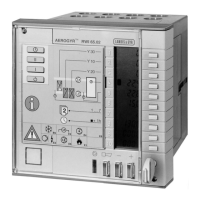
The controller consists of controller insert and base.
The controller insert accommodates all operating elements and the electronic circuits. It
is secured to the base by two screws which are designed such that they push the insert
away from the base when they are loosened.
The microprocessor with the memory, the associated electronic components, and the
display are carried by one printed circuit board, the relays by another. Another board
serves for communication and carries a specific microprocessor with the associated
interface. An EEPROM stores all setting values. In the event of a power failure, the
setting values are thus retained for an almost unlimited period of time. The reserve for
the weekly time switch (48 hours typically) is contained in the controller insert. For this
reason, the insert can be removed without having an effect on the actual time setting.
The base is made of plastic and is designed for both wall and flush panel mounting. In
the case of flush panel mounting, the controller is secured by a clamp. The base carries
four terminal blocks and a terminal strip for establishing the electrical connections with
the controller insert.
10
9
8
7
6
5
4
3
2
1
1 9 10 11
32 4 567 8
Set point heating
Set point cooling
Actual set point
Min. supply air temp.
Max supply air temp.
Day
Start time
Stop time
Data point number
Data point value
3205Z04E
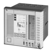
1 Front cover
2 Operating card 1 (for operating level 1) and operating instructions
3 Opening for acknowledgement of fault when front cover is closed
4 Connection facility for local network
5 Indicator lamp for plant status (ON/OFF)
6 Indicator lamp and acknowledge button for fault status signals
7 Setting buttons
8 Keyhole for opening the front cover (key enclosed)
9 Covering plate with operating card 2 (for operating levels 2 and 3)
10 Display with 10 lines
11 Function buttons
When the front cover is closed, the display shows (from top to bottom): Selection of
operating mode (solid square), manipulated variables, temperatures, weekday, time of
day, and status information.
The following setting choices exist (if enabled): Selection of operating mode (automatic,
on, standby), weekday, and summer- or wintertime.
RWI65.01 with front cover closed
Mechanical design
Display, setting and
operating elements
Legend
Operation with front cover
closed
(operating level 1)
10
9
8
7
6
5
4
3
2
1
3205Z16
I
B9
E3
E2
E5
E4
E1
E7
∆
∆∆
∆
P
+1h
1...7
2
Y 10
Y 20
Y 30
I
I
T
T
Landis & Staefa
RWI65.01
T
E8
I
 Loading...
