EasyManua.ls Logo

Siemens AEROGYR RWI65.01 User Manual

Siemens AEROGYR RWI65.01
18 pages
To Next Page IconTo Next Page
Page #1 background imageLoading...
Page #1 background image
Siemens Building Technologies CM2N3205E / 05.2001
Landis & Staefa Division 1/18
3
205
AEROGYR™
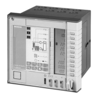
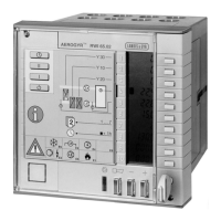
Controller RWI65.01
for cental air handling SW version 3.3
Operating voltage AC 24 V, signal voltage DC 0-10 V;
all control and monitoring functions in one unit;
major control tasks: temperature control, compensation, cascade control with
minimum/maximum limitation of supply air temperature, control of d.h.w. circuit;
Connection to Landis & Staefa building automation systems by means of
communication cards
Ventilating and air conditioning plants with:
Hot water or electric air heater batteries
Direct expansion cooler batteries or chilled water cooling
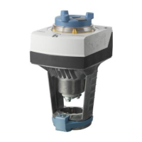
Valve and air damper actuators
Control units for thermal wheel type heat exchangers
Step switches for chillers and electric air heater batteries
Current valves for electric air heater batteries
Regulating units for heating, cooling or heat recovery
Auxiliary units for chillers or circulating pumps and fans
Signal converters for pneumatic/electric two- or three-position signals
Signal doublers and signal inverters
POLYGYR
®
(DC 0...10 V compatible)
UNIGYR
®
(DC 0...10 V compatible)
Name Type reference Remarks
FLN Communication card AZI65.1
1)
see data sheet 3206
LON/BACnet Communication card AZI65.2
1)
see data sheet 3207
LPB Communication card AZI65.3
1)
see data sheet 3208
Instructions set (de, fr, it) ARG65.40
2)
included, if ordered
Instructions set (en, sv, fi, no) ARG65.41
2)
included, if ordered
Instructions set (nl, es, da) ARG65.42
2)
included, if ordered
Instructions set (cs, sk, hu, pl, ru) ARG65.46
2)
included, if ordered
1) Optional
2) Consists of operating card 2, operating instructions, and mounting instructions
.
.
.
.
Use
Plants
Regulating units and
actuators
Accessories
Question and Answer IconNeed help?

Do you have a question about the Siemens AEROGYR RWI65.01 and is the answer not in the manual?

Siemens AEROGYR RWI65.01 Specifications

General IconGeneral
BrandSiemens
ModelAEROGYR RWI65.01
CategoryController
LanguageEnglish

Summary

Use and Applications

Plants Supported

Describes the types of ventilating and air conditioning plants the controller is used for.

Regulating Units and Actuators

Lists the regulating units and actuators compatible with the controller for system integration.

Functions and Features

Control and Monitoring Capabilities

Details the control and monitoring capabilities of the RWI65.01 controller for HVAC systems.

Communication Card Functionality

Explains the role and functionality of communication cards in large plant systems for data exchange.

Technical Design and Control Strategies

Control Logic and Operation

Explains automatic sensor identification, PI control, and operating action selection for the controller.

Compensation Methods

Describes outside temperature compensation and set value compensation methods for precise control.

Temperature Control Strategies

Details temperature control, cascade control, and supply air temperature control strategies.

Economizer Operation

Describes the economizer function for optimizing fresh air supply based on temperature differences.

Control Sequences

Explains the control sequences for air dampers and heat recovery systems.

Frost Protection

Details the frost protection operation for air heater batteries, including protective actions and sensor requirements.

Plant Operation and Monitoring

Plant Startup Procedures

Describes the procedures and prerequisites for switching the plant on, including operating modes.

Monitoring Plant Operations

Covers monitoring operations for plants with hot water and electric air heater batteries.

Efficiency Supervision

Explains the efficiency supervision for heat recovery systems, requiring additional sensors.

Time Switch Functionality

Details the weekly time switch function for programmable switching on/off times.

Fault Status Signals and Indication

Acknowledging Fault Status

Explains the procedure for acknowledging fault status signals and their indication on the unit.

Mechanical Design and User Interface

Display and Operating Elements

Describes the controller's display, setting buttons, and indicator lamps for operation.

Operation Modes

Details operation with the front cover closed (level 1) and open (levels 2 and 3).

Configuration and Connectivity

Controller Configuration with DIL Switches

Explains how to configure the controller settings using the internal DIL switches.

Communication Cards

Details the types of communication cards (FLN, LON/BACnet, LPB) supported by the controller.

Installation and Commissioning

Engineering and Installation Notes

Provides essential engineering and installation guidelines for the controller.

Commissioning Aids and Settings

Covers aids for commissioning, settings configuration, and important recommendations.

Technical Data

Power Supply and Inputs

Specifies the controller's power supply requirements and input signal characteristics.

Outputs and Protection

Details the controller's analog and relay outputs, and degree of protection ratings.

Environmental and Standards Compliance

Outlines environmental conditions and compliance with relevant product and EMC standards.

Diagrams and Data Points

Internal Diagram and Connections

Illustrates the controller's internal diagram and connection principles.

Wiring Connections

Provides detailed connection diagrams for sensors, remote units, and control signals.

List of Data Points

Lists all data points, their descriptions, ranges, and factory settings for configuration.

Miscellaneous Information

Heating Curve and Efficiency Supervision

Details heating curve parameters and efficiency supervision for heat recovery systems.

Fault Status Signal Flow Diagrams

Incoming Fault Status Signals

Illustrates the reaction of outputs to various incoming fault status signals.

Acknowledged Fault Status Signals

Shows the output reactions for acknowledged present fault status signals.
Dimensions