Power cabling Siemens Industry, Inc. • 23
24-hour support +1-800-877-7545 (Dial 2)
4. POWER CABLING
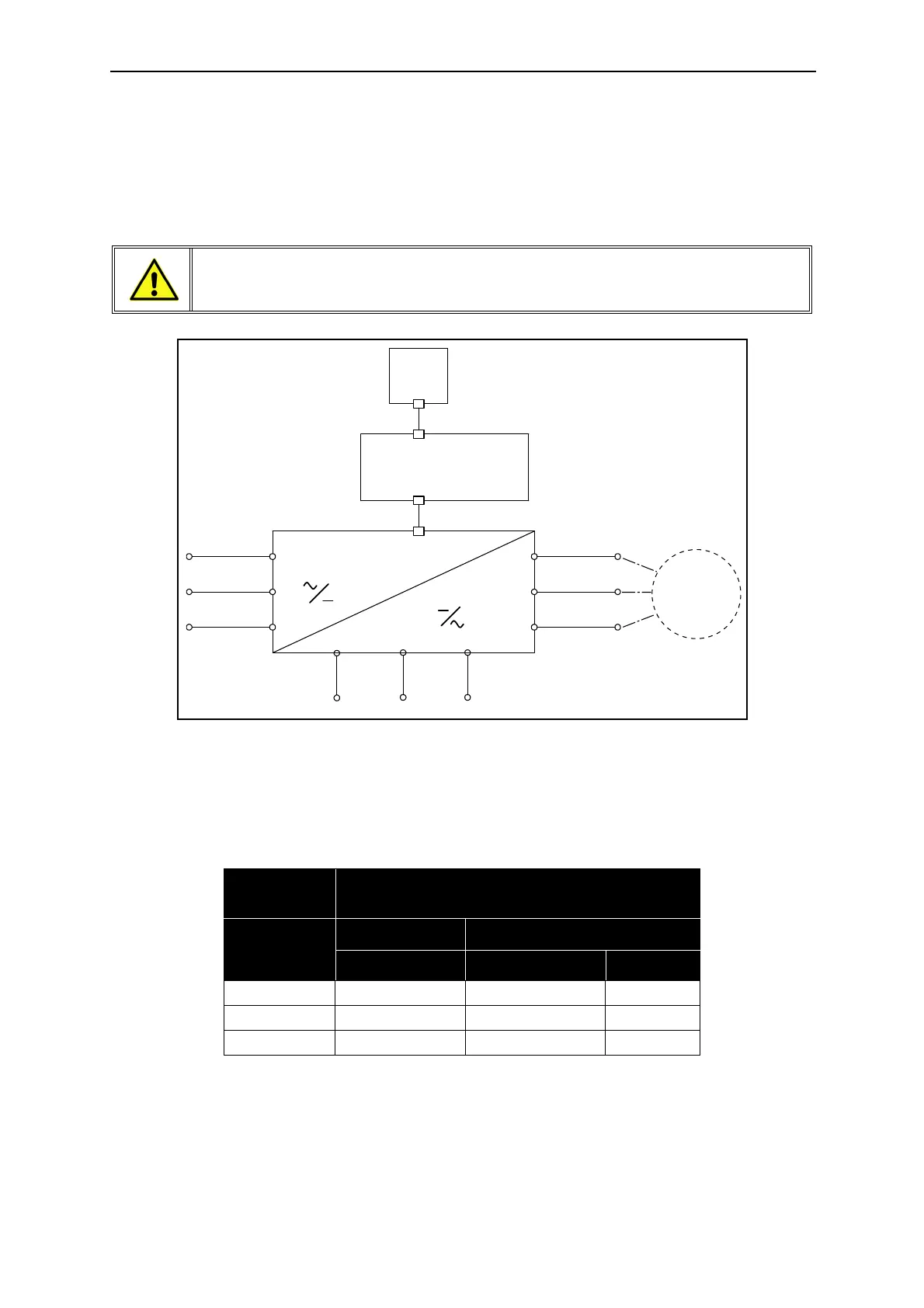
The mains cables are connected to terminals L1, L2 and L3 and the motor cables to terminals marked
with U, V and W. See principal connection diagram in Figure 16. See also Table 14 for the cable recom-
mendations for different EMC levels.
Figure 16. Principal connection diagram.
Use cables with heat resistance of at least +70 °C (158 °F). The cables and the fuses must be dimen-
sioned according to the drive nominal OUTPUT current found on the rating plate.
1 = Power cable intended for fixed installation and the specific mains voltage. Shielded
cable not required. (MCMK or similar recommended).
2 = Symmetrical power cable equipped with concentric protection wire and intended for the
specific mains voltage. (MCMK or similar recommended). See Figure 17.
NOTE: R+ and R- terminals are not used in the Siemens BT300 drive and external
components must not be connected to them.
Table 14. Cable types required to meet standards.
EMC levels
Cable type
1
st
environment 2nd environment
Category C2 Category C3 Level C4
Mains cable 1 1 1
Motor cable 3* 2 2
Control cable 4 4 4
U/T1
V/ T2
W/ T3
M
L1
L2
L3
DC-
DC+
9216.emf
Keypad
Cont r ol
Power unit
 Loading...