Do you have a question about the Siemens COMBIMASTER CM12 and is the answer not in the manual?
Details compliance with European Low Voltage, EMC, and Machinery Directives, listing relevant standards.
Lists UL CUL and UR recognized power conversion equipment certifications and their usage requirements.
Mentions Siemens plc's adherence to ISO 9001 quality management system requirements.
Provides guidelines for grounding, screened leads, cable separation, and contactor suppression for EMI reduction.
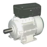
Instructions for mechanical installation of COMBIMASTER, including lifting, mounting, and shaft balancing.
Guidelines for mechanical installation of MICROMASTER Integrated, referencing other Siemens documents.
Details electrical connections for MICROMASTER Integrated, showing star and delta configurations.
Instructions for electrical installation for both product lines, including cover removal and circuit board caution.
Guidance on connecting mains power cables, including voltage, current, wire type, and terminal connections.
Explains how to connect control cables, including separation, screening, and specific terminal connections with diagrams.
Covers basic operation, requirements for advanced operation (OPm2), and initial power-on procedures.
Details two modes of operation: using the internal potentiometer and using a potentiometer with a run/stop switch.
Explains how to control the inverter using an external potentiometer or a 0-10V signal.
Describes operation using a Clear Text Display (OPm2) or serial link for startup and digital setpoint configuration.
Explains methods for stopping the motor using an external switch or the potentiometer.
Provides a guide to check inverter LEDs to diagnose startup issues and explains how to handle faults and warnings.