10 © Siemens plc1999 | G85139-H1731-U400-D2
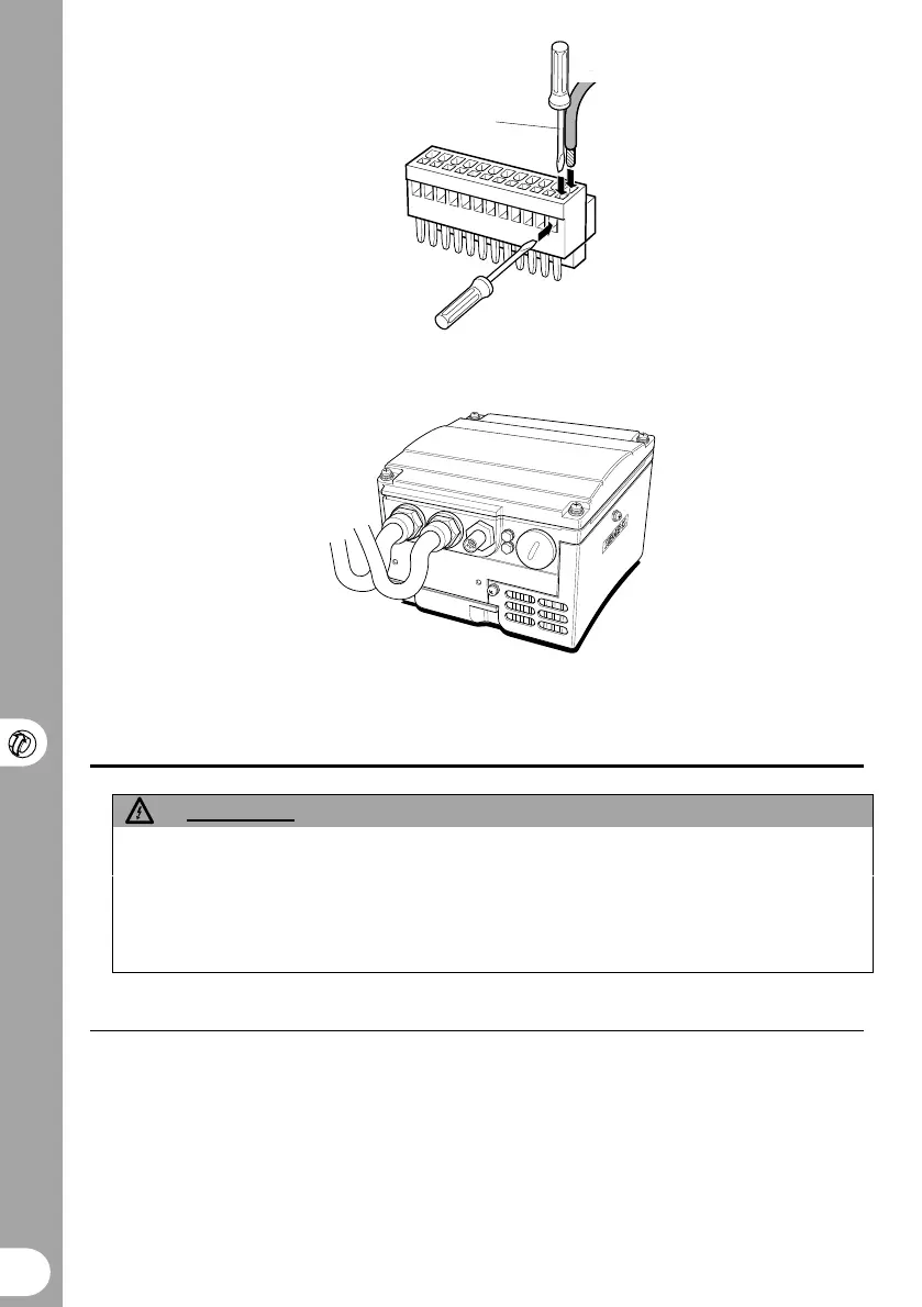
1.8mm max. screwdriver
Figure 5 Connecting Control Wires to PL800
Figure 6 Cable Connections with Drip Loop
DRIVE OPERATION
WARNING
The equipment must not be switched on until after its cover has been fitted and the
cover screws have been tightened to the correct torque (see Fig. 2 & 3).
After the power has been turned off, you must always wait five minutes so that the dc
link capacitors can discharge. Do not remove the cover until this time has elapsed.
All settings must be only entered by qualified personnel, paying particular attention to
the safety precautions and warnings.
General
For basic operation of COMBIMASTER, no
additional equipment is required. However,
for more complex operation, OPm2 – Clear
Text Display is required (OPm2 is available
as an option, but must be ordered
separately).
The inverter does not have a mains power
switch and is therefore live when the mains
supply is connected.
When delivered, the inverter has a frequency
setpoint range of between 0 Hz and 50 Hz.
Regardless of its initial position, internal
potentiometer R314 must be turned fully
counter-clockwise before it will start the
inverter.