CPUs
1-51
PLC S7-300, CPU Specifications CPU 312 IFM to CPU 318-2 DP
A5E00111190-01
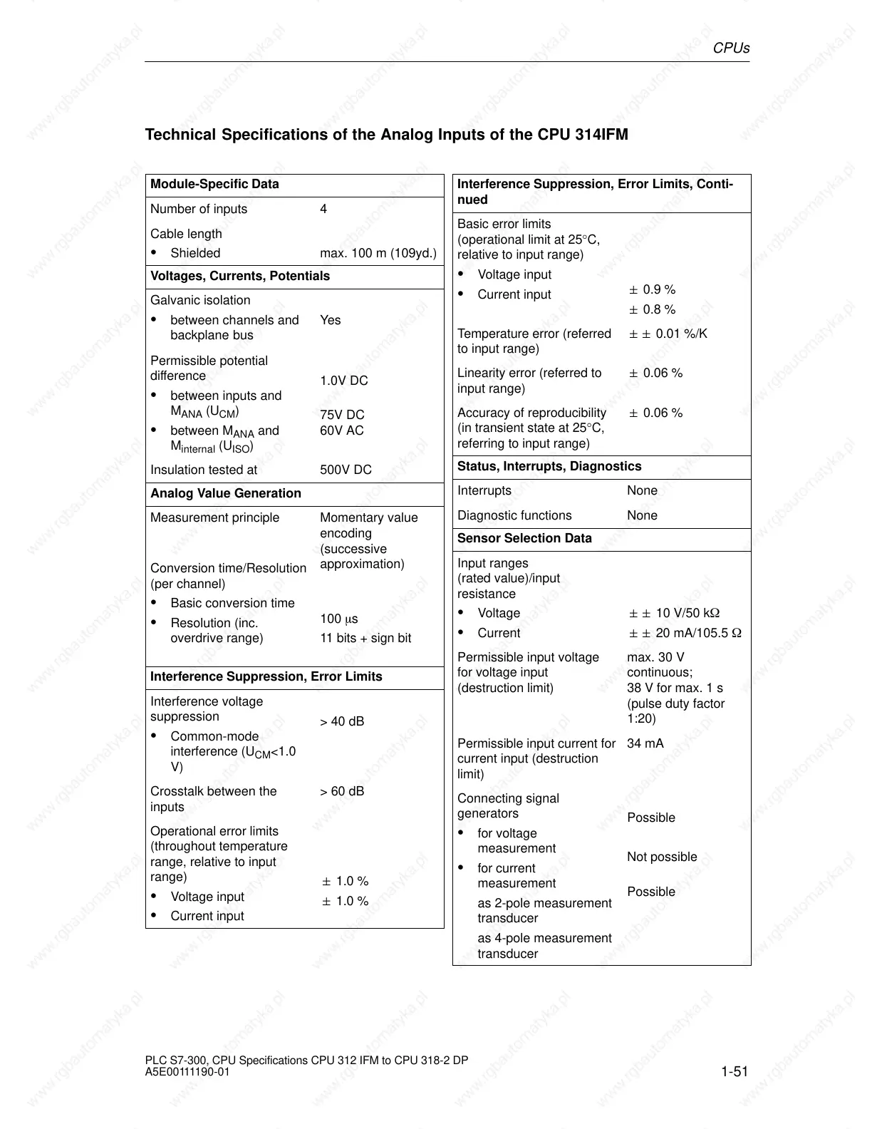
Technical Specifications of the Analog Inputs of the CPU 314IFM
Module-Specific Data
Number of inputs 4
Cable length
Shielded max. 100 m (109yd.)
Voltages, Currents, Potentials
Galvanic isolation
between channels and
backplane bus
Yes
Permissible potential
difference
between inputs and
M
ANA
(U
CM
)
between M
ANA
and
M
internal
(U
ISO
)
1.0V DC
75V DC
60V AC
Insulation tested at 500V DC
Analog Value Generation
Measurement principle
Conversion time/Resolution
(per channel)
Basic conversion time
Resolution (inc.
overdrive range)
Momentary value
encoding
(successive
approximation)
100 s
11 bits + sign bit
Interference Suppression, Error Limits
Interference voltage
suppression
Common-mode
interference (U
CM
<1.0
V)
> 40 dB
Crosstalk between the
inputs
> 60 dB
Operational error limits
(throughout temperature
range, relative to input
range)
Voltage input
Current input
1.0 %
1.0 %
Interference Suppression, Error Limits, Conti-
nued
Basic error limits
(operational limit at 25°C,
relative to input range)
Voltage input
Current input
0.9 %
0.8 %
Temperature error (referred
to input range)
0.01 %/K
Linearity error (referred to
input range)
0.06 %
Accuracy of reproducibility
(in transient state at 25°C,
referring to input range)
0.06 %
Status, Interrupts, Diagnostics
Interrupts None
Diagnostic functions None
Sensor Selection Data
Input ranges
(rated value)/input
resistance
Voltage
Current
10 V/50 k
20 mA/105.5
Permissible input voltage
for voltage input
(destruction limit)
max. 30 V
continuous;
38 V for max. 1 s
(pulse duty factor
1:20)
Permissible input current for
current input (destruction
limit)
34 mA
Connecting signal
generators
for voltage
measurement
for current
measurement
as 2-pole measurement
transducer
as 4-pole measurement
transducer
Possible
Not possible
Possible
 Loading...

