CPU 31x-2 as DP Master/DP Slave and Direct Communication
2-4
PLC S7-300, CPU Specifications CPU 312 IFM to CPU 318-2 DP
A5E00111190-01
2.2 DP Address Areas of the CPUs 31x-2
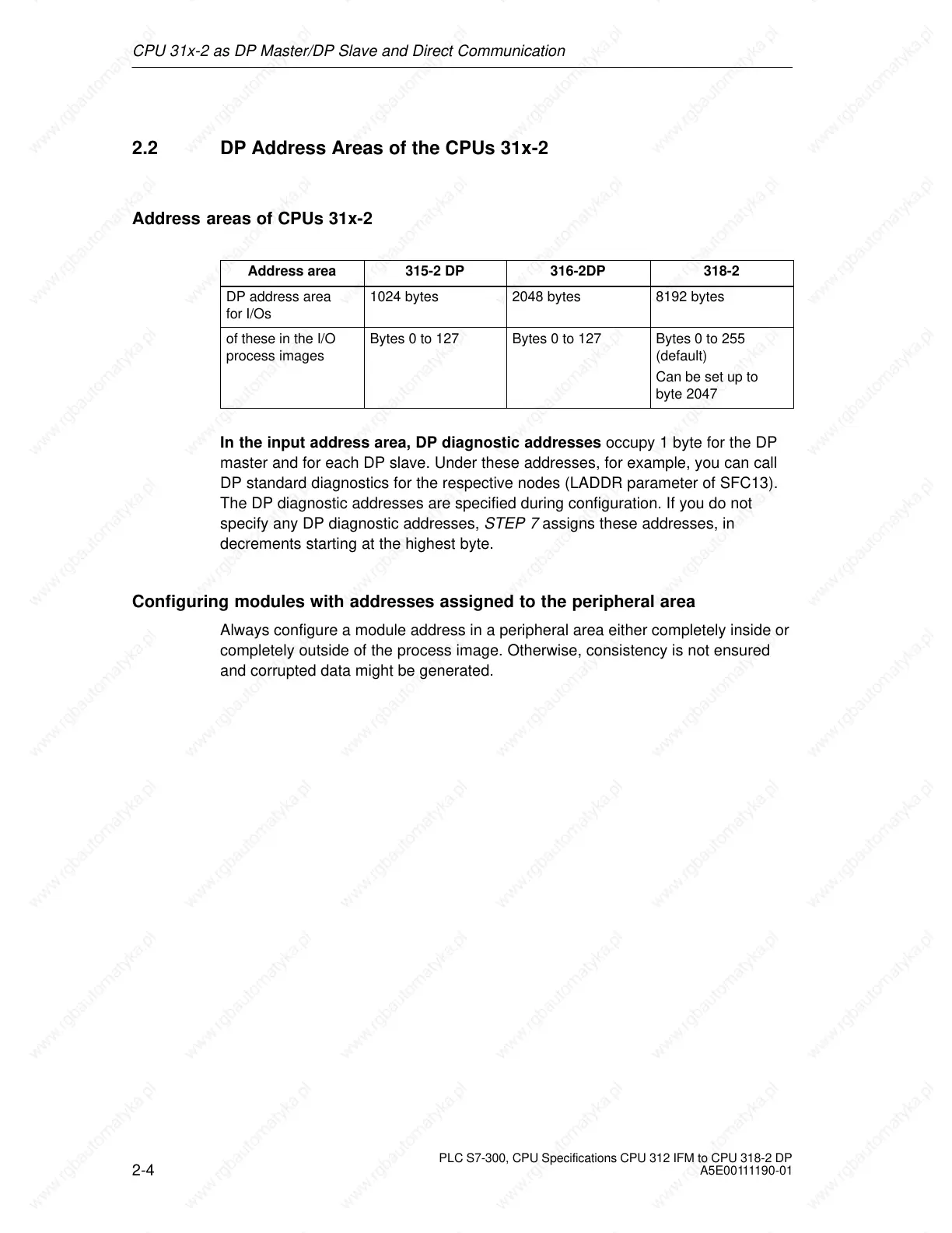
Address areas of CPUs 31x-2
Address area 315-2 DP 316-2DP 318-2
DP address area
for I/Os
1024 bytes 2048 bytes 8192 bytes
of these in the I/O
process images
Bytes 0 to 127 Bytes 0 to 127 Bytes 0 to 255
(default)
Can be set up to
byte 2047
In the input address area, DP diagnostic addresses occupy 1 byte for the DP
master and for each DP slave. Under these addresses, for example, you can call
DP standard diagnostics for the respective nodes (LADDR parameter of SFC13).
The DP diagnostic addresses are specified during configuration. If you do not
specify any DP diagnostic addresses, STEP 7 assigns these addresses, in
decrements starting at the highest byte.
Configuring modules with addresses assigned to the peripheral area
Always configure a module address in a peripheral area either completely inside or
completely outside of the process image. Otherwise, consistency is not ensured
and corrupted data might be generated.
 Loading...

