Operating and display elements
2.1 Operating and display elements: CPU 31xC
CPU 31xC and CPU 31x, Technical Data
2-2 Manual, 01/2006 Edition, A5E00105475-06
The figures show the following CPU elements
(1) Status and error displays
(2) Slot for the SIMATIC Micro Memory Card (MMC) incl. the ejector
(3) Connections of the integrated I/O.
(4) Power supply connection
(5) 2. Interface X2 (PtP or DP)
(6) 1. Interface X1 (MPI)
(7) Mode selector switch
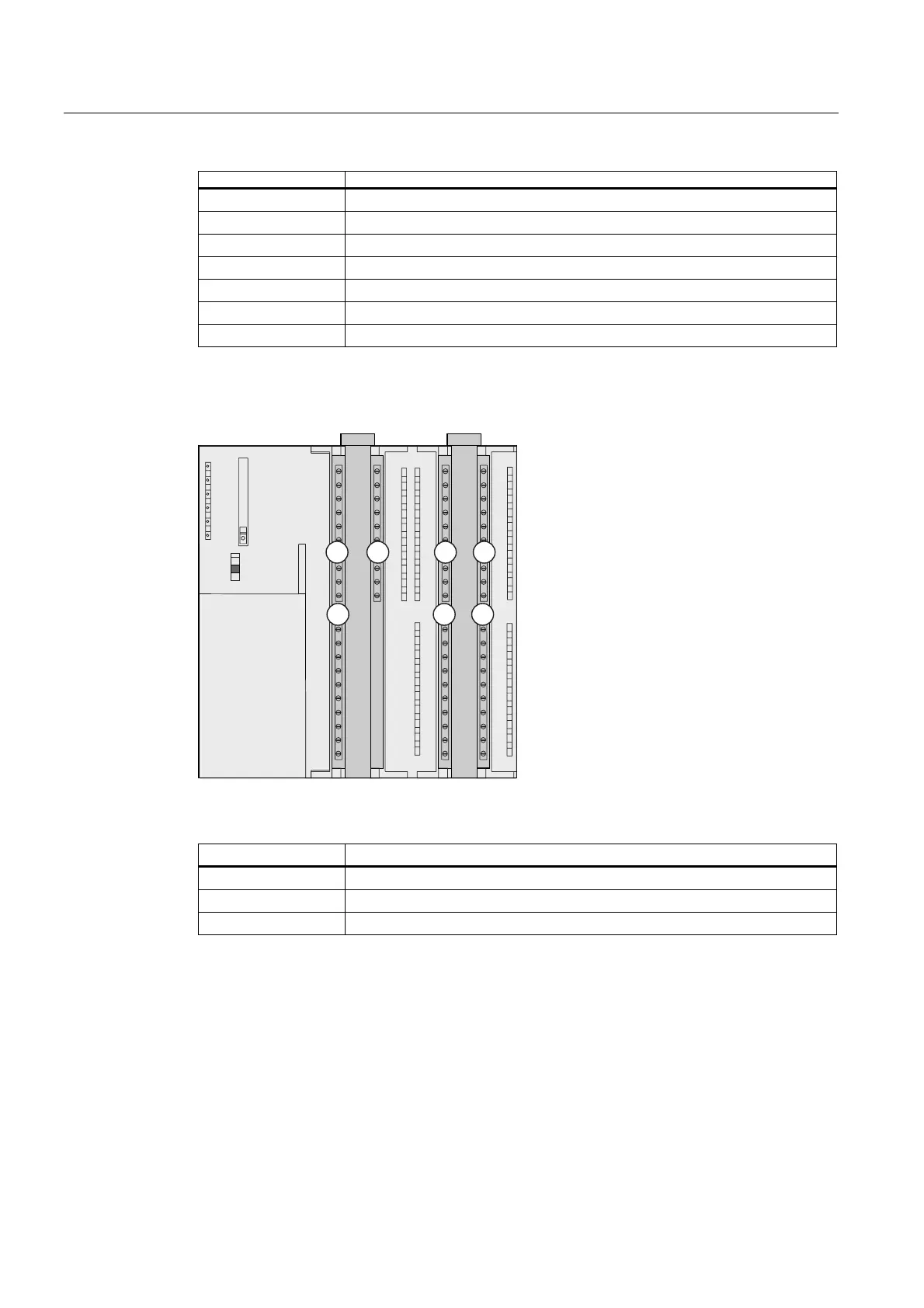
The figure below illustrates the integrated digital and analog I/Os of the CPU with open front
covers.
581
6723
05(6
6)
%)
'&9
)5&(
581
; ;
2
21 3
1 2 3
6723
Figure 2-1 Integrated I/Os of CPU 31xC (CPU 314C-2 PtP, for example)
The figures show the following integrated I/Os
(1) Analog I/Os
(2) each with 8 digital inputs
(3) each with 8 digital outputs
 Loading...