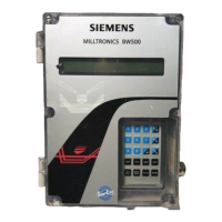
Specifications Page: 19 Power Details on AC and DC power requirements and fuse specifications.
Application Information on compatible scales and sensors for the BW500 and BW500/L.
Accuracy Specifies the accuracy rating for the device.
Environmental Details on operating location, altitude, temperature, and humidity.
Enclosure Information about the enclosure type, dimensions, and material.
Programming Methods available for programming the device.
Display Description of the liquid crystal display capabilities.
Memory Details on program and parameter storage and battery backup.
Inputs Specifications for load cell, speed sensor, mA, and auxiliary inputs.
Outputs Specifications for mA, load cell, speed sensor, remote totalizer, and relay outputs.
Cable Specifications for cable types and lengths for various connections.
Options Information on optional components like speed sensors and communication modules.
Installation Page: 23 Dimensions Provides physical dimensions of the unit and mounting hole details.
Layout Diagram illustrating the internal layout of components and their locations.
Optional Plug-ins Instructions for installing optional modules like SmartLinx and mA I/O board.
Interconnection General guidelines and diagrams for connecting the unit to other devices.
Auxiliary Inputs Details on connecting and programming auxiliary input functions.
Auto Zero Description of the auto zero calibration function.
RS232 Port 1 Wiring and connection details for the RS232 port.
mA Output 1 Specifications and connection for the mA output.
Relay Output Details on connecting and assigning functions to relay outputs.
RS485 Port 2 Wiring and connection details for the RS485 port.
RS232 Port 3 Wiring and connection details for the RS232 port.
Recalibration Page: 68 Material Tests Methods for verifying span calibration accuracy and compensating for material flow.
Design Changes Explains the impact of parameter changes on calibration effectiveness.
Routine Zero Step-by-step instructions for performing a routine zero calibration.
Initial Zero Procedure for performing an initial zero calibration when required.
Direct Zero Method for directly entering the zero reference count.
Auto Zero Explanation of the automatic zero calibration function.
Routine Span Step-by-step instructions for performing a routine span calibration.
Initial Span Procedure for performing an initial span calibration when required.
Direct Span Method for directly entering the span reference count.
Multispan Functionality for calibrating the unit for multiple feed conditions.
Online Calibration Feature for checking and adjusting span calibration without interrupting material flow.
Factoring Method for calculating test load values against a new reference.
Linearization Procedure to compensate for non-linear responses in the weighing system.
Operation Page: 99 Load Sensing Requirement for a load signal to calculate rate and totalize material flow.
Speed Sensing Requirement for a speed signal for accurate rate and totalization.
Damping Controls the response speed of displayed readings and output functions.
Relay Output Assignment of relays to alarm functions and their operation.
Totalization Functionality for accumulating material flow based on belt speed and load.
Glossary Page: 209 Auto Zero Definition of the automatic zero calibration function.
Batching Definition of accumulating a predetermined quantity of material.
Contacts Definition of electrical conductor junctions in open or closed states.
Damping Definition of control over response speed of readings and output functions.
Design Rate Definition of maximum material flow rate for an application.
Direct Span Definition of entry of previously recorded span value.
Direct Zero Definition of entry of previously recorded zero value.
Factoring Calculation of test load value using current span as reference.
Inclinometer Device that accepts incline information about conveyor or scale.
Initial Span Reference span for determining deviation of other spans.
Initial Zero Reference zero for determining deviation of other zeros.
Linearization Compensation for non-linear output caused by varying load rates.
Load Cell Strain Gauge transducer proportional to applied force.
LVDT Electromechanical transducer for displacement measurement.
mA Unit of measure for current flow, milliamperes.
Material Test Material samples used to verify span calibration accuracy.
Modbus Industry standard protocol for SCADA and HMI systems.
Multispan Calibration required for each material to realize maximum accuracy.
PID Proportional Integral Derivative control for feed rate adjustment.
Relay Electromechanical device with contacts that can be closed or opened.
Setpoint Value the integrator tries to match.
SmartLinx Interface to popular industrial communication systems.
SPA Single Parameter Access for viewing or editing parameters.
Span Count value representing mV signal at 100% design load.
Span Register Count of span calibrations performed since last master reset.
Test Weight Calibrated weight representing a certain load on the scale.
Totalizer Incremental counter recording total material monitored.
Zero Register Count of zero calibrations performed since last master reset.


