Installation
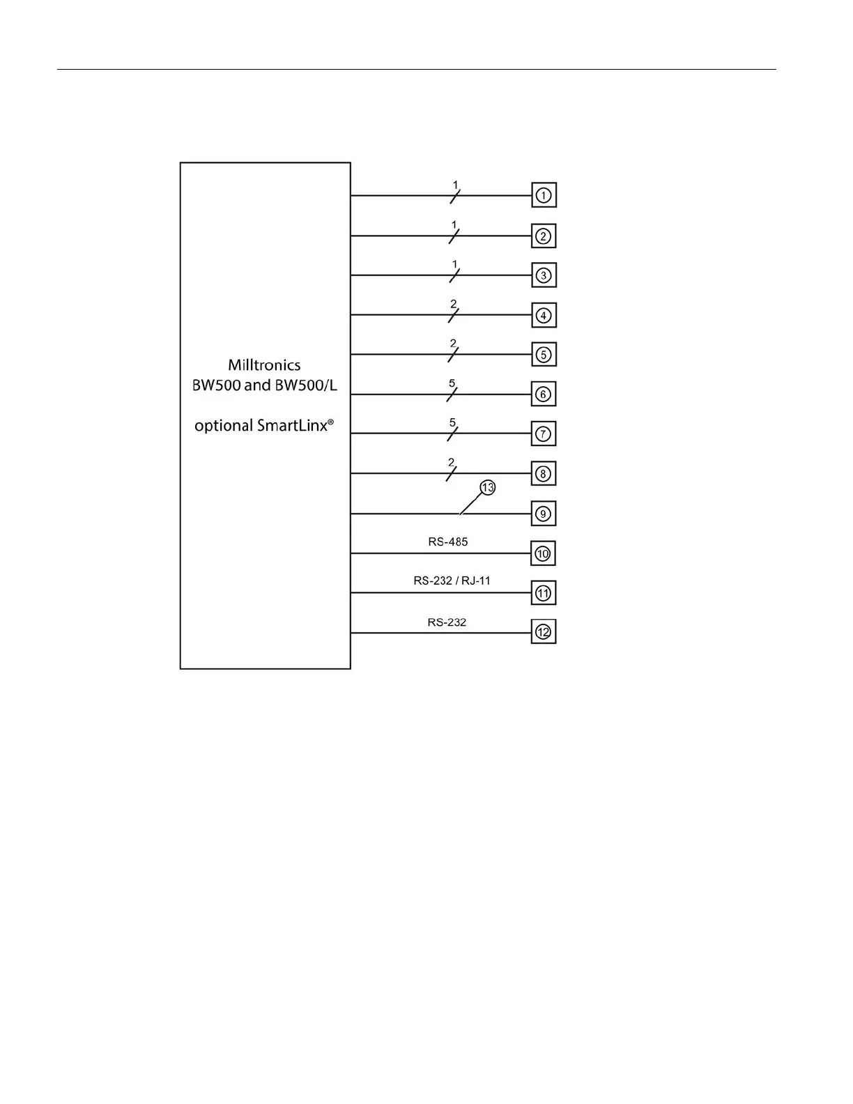
5.4 Interconnection
BW500 and BW500/L
28 Operating Instructions, 12/2016, A5E33482052-AD
Belt scale, see Specifications (Page 17)
Speed sensor, optional, see Specifications (Page 17)
mA output to customer device
mA output to customer device (optional I/O board required)
mA input from customer device (optional I/O board required)
Relay output, to customer device (2 for BW500/L)
Customer remote totalizer
Optional fieldbus connection (SmartLinx card required)
Communication ports can be configured for Siemens Milltronics Dolphin Plus, print data, or
Modbus ASCII or RTU protocol
Communication ports can be configured for Siemens Milltronics Dolphin Plus, print data, or
Modbus ASCII or RTU protocol
Communication ports can be configured for Siemens Milltronics Dolphin Plus, print data, or
Modbus ASCII or RTU protocol