OPERATION Each DAC-NET occupies one card slot in the CC-5/CC-2 card cage. Only the
left connector of the CC-5/CC-2 contains the signals to the CPC-DAC
interface. The connection from the PMI/PMI-2/PMI-3 to the CC-5/CC-2, in
which the DAC-NET is mounted, must be on the left side of the CC-5/CC-2.
D-NET
The D-NET Main In / Return Out and Main Out / Return In are isolated from
each other and from the DAC-NET. This allows the use of different power
sources with different ground references. The DAC-NET is able to detect
ground faults and data faults of each D-NET section. Each DAC-NET sends and
receives a data stream consisting of digital audio stream and control data. The
baud rate is 1.536 Mbps.
NOTE:
Class B/Style 4 = ULC DCLB
Class X/Style 7 = ULC DCLC
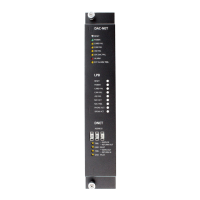
Class B The node with the lowest node number (master) sends the data stream from
Main Out to Main In at the next node. The last node combines Main In with
Return Out and returns the data stream back. When the data stream comes
back to the node with the lowest node number this node combines Return In
with Main Out and sends it to Main In of the next node.
Figure 2
DAC-NET D-NET Class B
In a Class B configuration, two unshielded twisted pairs are required. They
can be in one cable.
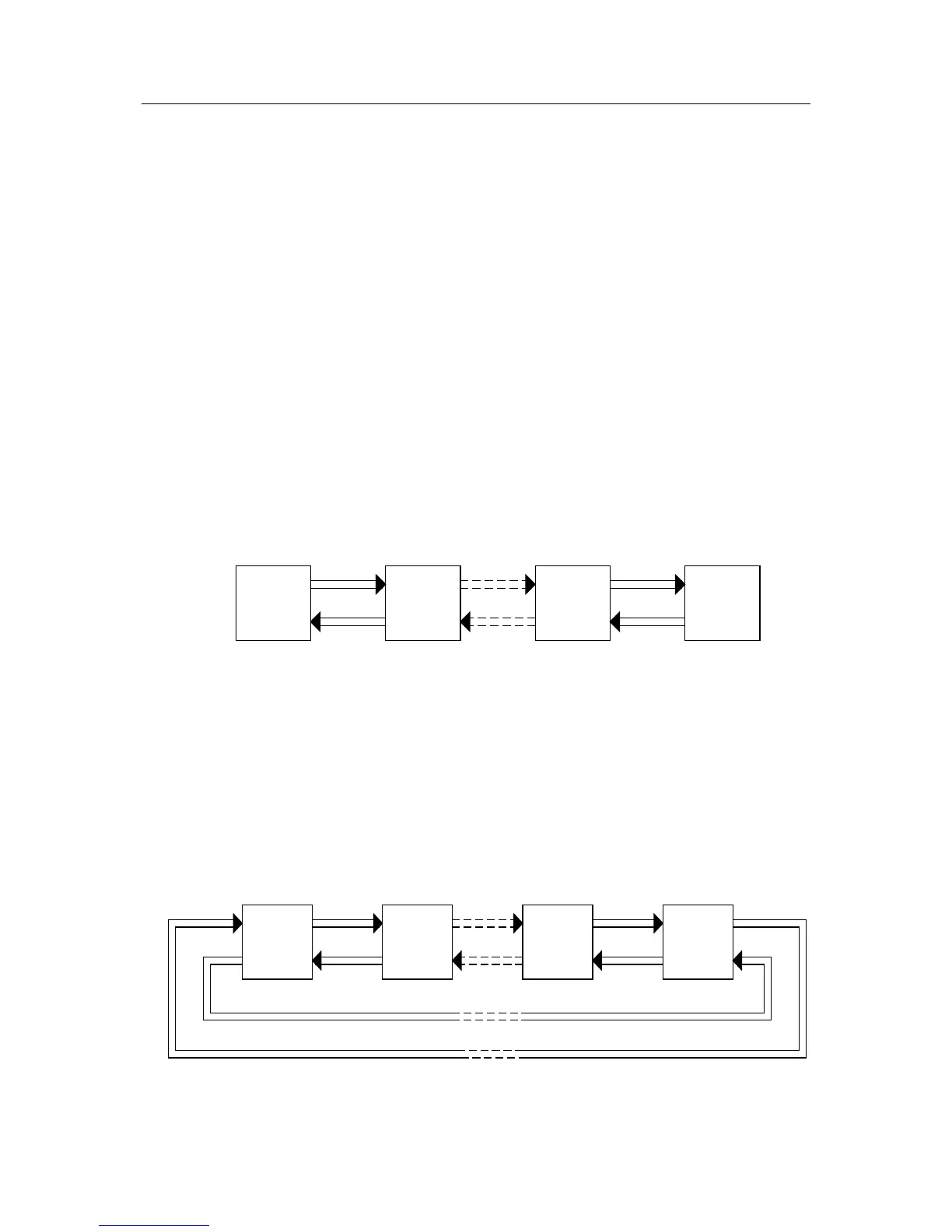
Class X In a Class X configuration, the master sends the data stream by using Main
Out / Main In in a loop. The Return Out / Return In loop contains only a test
data stream for supervision.
Figure 3
DAC-NET D-NET Class X
 Loading...