9.11 Diver operated connectors mating and de-mating ......................................................... 40
10 CUSTOMER COMMENTS/FEEDBACK ........................................................................................ 42
Tables
Table 1 List of other Installation, Operation and Maintenance manuals related to
DigiTRON product range ....................................................................................... 5
Table 2 DigiTRON product range identification ............................................................... 6
Table 3 DigiTRON product specification and certification ............................................. 7
Table 4 DigiTRON product contact details ....................................................................... 8
Table 6 Troubleshooting product contact details.......................................................... 33
Illustrations
Figure 1 Product advice label .............................................................................................. 8
Figure 2 Product marking on DigiTRON product .............................................................. 9
Figure 3 Typical flange mounted connector ...................................................................... 9
Figure 4 Typical ROV bulkhead connectors .................................................................... 10
Figure 5 Typical Flying and Flanged ROV dummy connectors ..................................... 10
Figure 6 Typical Diver-operated dummy parking connectors ....................................... 10
Figure 7 Acceptable packaging for shipment .................................................................. 20
Figure 8 Unacceptable packaging and storage ............................................................... 20
Figure 9 Typical stab-plate connector .............................................................................. 24
Figure 10 Flange styles for stab-plate connectors............................................................ 25
Figure 11 Typical bulkhead ROV connectors .................................................................... 27
Figure 12 ROV bulkhead connector sectional view .......................................................... 27
Figure 13 Typical compliant flange-mounted ROV connector ......................................... 28
Figure 14 Installation of compliant flange-mount ROV plug ............................................ 28
Figure 15 Sectional view to show installation and parts of compliant flange-mount
connector 29
Figure 16 View to show ROV compliant mount flange text ............................................. 29
Figure 17 Sealed bulkhead diver mate plug connector .................................................... 30
Figure 18 Typical flange mounted dummy and parking connectors .............................. 31
Figure 19 Test connectors, ROV, Diver and Stab-plate type ........................................... 32
Figure 21 ROV-type Transport Caps (left) and Protective Caps ...................................... 35
Figure 22 ROV-type Subsea Caps ....................................................................................... 36
Figure 23 ROV-type Subsea Environmental Cap and Dummy Connectors, flying and
flanged types. ....................................................................................................... 36
Figure 24 Alignment marks and lip seal mating indicator ................................................ 38
Figure 25 ROV de-mate tool, part number BQ-30090-00 .................................................. 39
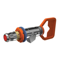
Figure 26 Diver operated connector showing mating features ....................................... 41
 Loading...