
M
Michelle ShieldsJul 25, 2025
What to do if Siemens DigiTRON product failing to operate correctly?
- VVeronica WilsonJul 25, 2025
If your Siemens cables and connectors product isn't working right, please contact Siemens Energy for assistance.
What to do if Siemens DigiTRON product failing to operate correctly?
If your Siemens cables and connectors product isn't working right, please contact Siemens Energy for assistance.
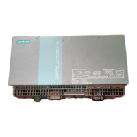
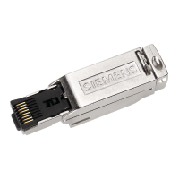
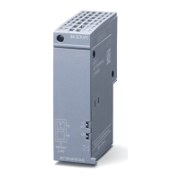
Overview of DigiTRON connectors for subsea applications and low voltage links.
Details technical specifications and product certifications for DigiTRON connectors.
Provides contact information for support, safety, and feedback channels.
Describes the safety advice label attached to Siemens Energy subsea products.
Explains the marking on DigiTRON products, including part numbers and ratings.
Details the CE label requirements and applicable directives for product compliance.
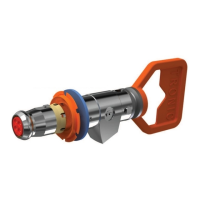
Shows examples of DigiTRON connectors, including flange mounted types.
Classifies action-related warnings based on danger severity using symbols and signal words.
Defines the intended application of DigiTRON connectors as low voltage electrical systems for subsea use.
Provides essential safety guidelines for installation, operation, and maintenance.
Details dangers arising from incorrect operation and misuse of the product.
Highlights risks of death from electric shock due to exposed live pins and unscreened cables.
Warns about injuries and damage from incorrect testing, maintenance, or repairs.
Addresses risks associated with manual handling, lifting, and carrying of products.
Lists relevant documents and legislation for safe installation and operation.
Addresses health and safety assessments for hazardous substances used in DigiTRON products.
Presents detailed technical specifications for DigiTRON connectors across different types.
Details how to protect and package DigiTRON connectors for transport and storage.
Provides instructions on how to unpack connectors, emphasizing care to avoid damage.
Covers storage conditions, protection methods, and end-of-life considerations for connectors.
Advises on proper storage conditions for short-term periods.
Provides guidelines for storing connectors for extended periods.
Refers to specific document for storage of elastomeric components.
Instructions for repackaging products for return or transport to prevent damage.
Guidelines for the safe disposal and recycling of waste and end-of-life products.
Explains cathodic protection requirements for different types of DigiTRON connectors.
Lists the required tooling for installation of DigiTRON connectors.
Details installation considerations for stab-plate connectors.
Describes the non-removable Solid Fixed flange and its mounting instructions.
Describes the non-removable Solid Floating flange and its mounting instructions.
Describes the removable Split Fixed flange and its mounting instructions.
Describes the removable Split Floating flange and its mounting instructions.
Instructions for installing bulkhead mounted ROV connectors.
Step-by-step guide for installing ROV bulkhead connectors.
Instructions for installing compliant flange-mounted ROV connectors.
Instructions for installation of flange-mounted diver-operated connectors.
Details the mounting process for flange-mounted diver-operated connectors.
Instructions for installing sealed bulkhead diver connectors.
Information on the installation of dummy and parking connectors.
Guidelines and precautions for testing DigiTRON connectors.
Instructions for installing cable tails onto DigiTRON connectors.
States that there are no visible or audible signals during product use.
Describes normal operation and lists indications of product faults.
Provides contact information for troubleshooting product issues.
Advises users to read section 3 on product safety before use.
States that DigiTRON products require zero maintenance and are not user serviceable.
Details measures to protect receptacle contact pins from corrosion and damage in subsea environments.
Describes various caps and dummy connectors for product protection during use.
Explains the use of transport and protective caps for topside applications.
Details the types and uses of subsea protective caps and dummy connectors.
Provides advice and warnings regarding mating and de-mating connectors while energized.
Provides instructions for removing marine growth and calcareous deposits using Citric Acid.
Refers to section 7.2.5 for product testing information.
Outlines checks to perform before mating connectors, including debris and damage inspection.
Details the process for mating and de-mating ROV connectors.
Explains how to align and mate ROV connectors using alignment marks.
Refers to section 5.1 for maximum misalignment values and mating forces for ROV connectors.
Describes checks to perform after mating ROV connectors.
Details the procedure for de-mating ROV connectors, including tool usage.
Covers mating and de-mating procedures for stab-plate connectors.
Explains how stab-plate connectors are mated and de-mated without a latching mechanism.
Discusses risks and procedures for partial disconnection and interrupted connections.
Details mating and de-mating procedures for diver operated connectors.
Describes the mating and de-mating process for diver operated connectors using a clamp ring.
Explains self-alignment design for diver operated connectors.
Describes how to check for full engagement of diver operated connectors.
| Brand | Siemens |
|---|---|
| Model | DigiTRON Series |
| Category | Cables and connectors |
| Language | English |