Do you have a question about the Siemens FC2050 and is the answer not in the manual?
Observes safety notices to protect people and property, including symbols and signal words.
Covers national standards, legislation, and electrical installation safety regulations.
Lists the minimum hardware required for FS20 panels in marine applications.
Describes the FS20 system's software and the need for configuration and testing.
Covers spot-type and smoke detector installation considerations and best practices.
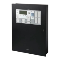
Details the FH2071-UM enclosure, its design, and features for marine applications.
Provides step-by-step instructions for mounting the FH2071-UM enclosure.
Outlines prerequisites and steps for laying and connecting the power supply safely.
Provides instructions for safely laying and connecting the mains cable to the power supply.
Provides instructions and notices for safely installing BP-62 batteries.
Details wiring installation procedures, including knockout usage and ferrite placement.
Details jumper settings and terminal block connections for power supply and battery.
Describes the connection and configuration of the power supply to the X301 terminal block.
Details the connection process for the battery harness to the X303 terminal.
Provides instructions for installing the periphery board onto the back box using screws.
Illustrates wiring diagrams for connecting notification devices as Class A or Class B circuits.
Describes detector circuits, circuit drivers, and their wiring configurations.
Provides step-by-step instructions for installing the FCA2015-U1 DACT module.
Provides step-by-step instructions for installing the FN2001-U1 network module.
Details pin assignments for connector X3 and wiring configurations for Class A and B networks.
Provides pin assignments for connector X3 used in Class A SAFEDLINK network wiring.
Details how to install the FCA2016-U1 RS-485 module into specified slots.
Provides pin assignments for plug X2 on the FCA2016-U1 RS-485 module.
Details how to install the FCI2011-U1 NAC module onto the periphery board.
Details pin assignments for NAC 2 Class A and Class 2-1/2-2 Class B terminal blocks.
Details how to install the XCI2001-U1 releasing module onto the periphery board.
Details pin assignments for the X5 plug connection for releasing relay outputs.
Provides step-by-step instructions for installing the FT2015 terminal.
Details wiring from the remote terminal to the RS-485 circuit for Class B and Class A configurations.
Details connection terminals X5 (NET_OUT) and X6 (NET_IN) for RS-485 circuits.
Guides through initial panel preparation, including connections and startup checks.
Steps for preparing the panel for commissioning when BDV installation is not performed.
Details the process for auto-configuring the panel using the Topology menu.
Provides steps and notices for auto-configuring detector circuits, especially Class A circuits.
Outlines steps for commissioning standalone or network panels using manual configuration.
Details commissioning variants combining manual and auto-configuration methods.
Procedure for commissioning standalone panels using auto-configuration without a PC.
Prerequisites and steps for integrating a new panel into an existing site.
Instructions for temporarily removing and re-inserting a single device base.
Steps for temporarily removing multiple devices, emphasizing correct re-insertion.
Procedure for permanently removing devices, including deletion from configuration.
| Model | FC2050 |
|---|---|
| Manufacturer | Siemens |
| Storage Temperature | -20 °C to +60 °C |
| Protection Class | IP30 |
| Type | Control Panel |
| Input Voltage | 230V AC |
| Power Supply | battery backup |
| Network Capability | Yes |
| Communication Interface | RS-485 |
| Display | LCD |
| Keypad | Yes |