M
Michael ReynoldsSep 8, 2025
What does 'CircuitTrouble' mean on my Siemens FC901-U3?
- CCourtney HarrisonSep 9, 2025
If your Siemens Control Panel indicates circuit trouble, it means the battery charge circuit is in trouble.
What does 'CircuitTrouble' mean on my Siemens FC901-U3?
If your Siemens Control Panel indicates circuit trouble, it means the battery charge circuit is in trouble.
What does it mean if my Siemens FC901-U3 says 'Short'?
If your Siemens Control Panel indicates a short, it means the device is experiencing a short trouble.
What does it mean if my Siemens Control Panel indicates a ground fault?
If your Siemens Control Panel shows a ground fault, it indicates the device is in a ground fault condition.
What does it mean when my Siemens FC901-U3 Control Panel displays 'VoltageLow'?
If your Siemens Control Panel indicates a low voltage, it means the battery voltage is too low.
What does it mean when my Siemens Control Panel displays 'VoltageHigh'?
If your Siemens Control Panel displays a high voltage warning, it indicates that the battery voltage is too high.
What does 'BatteryAbsent' mean on my Siemens Control Panel?
If your Siemens Control Panel indicates that the battery is absent, it means the battery is missing.
What does 'AddressUnspecified' mean on my Siemens FC901-U3?
If your Siemens Control Panel displays 'AddressUnspecified', it means that the SLC device has no address.
What does 'MessageLost' mean on my Siemens FC901-U3?
If your Siemens Control Panel indicates 'MessageLost', it means the DACT lost some messages because of limited memory space.
What does 'FatalFault' mean on my Siemens FC901-U3 Control Panel?
If your Siemens Control Panel reports a fatal fault, it means the SLC device reported a fatal fault trouble.
What does 'TypeMismatch' mean on my Siemens Control Panel?
If your Siemens Control Panel displays 'TypeMismatch', it means the SLC device type is not consistent with the config file.
Defines the operational and electrical limitations of the control panel.
Crucial notices for all parties involved in the system's use and installation.
Provides context, standards, and contact information for the manual.
Important warnings regarding FCC compliance for telephone network connections.
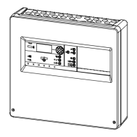
Provides a comprehensive overview of the FC901 control panel system's features.
Details the specifications and function of the control panel's power supply.
Describes the Signaling Line Circuit's capacity and operation.
Details the two independent Notification Appliance Circuits (NACs).
Information on the Serial Interface Circuit (UFP) and connected devices.
Explains the function and rating of the panel's four status relays.
Details the USB programming port for panel configuration.
Description of the integrated Digital Alarm Communicator Transmitter.
Lists and describes optional modules like City Tie and Remote Printer.
Explains the features and operation of serial LCD annunciators.
Details the FT Series LED driver and annunciator options.
Describes the functionality and configuration of addressable smoke detectors.
Details the use and programming of addressable heat detectors.
Covers addressable modules for monitoring and control functions.
Information on addressable manual pull stations.
Description of intelligent supervised audible sounder bases.
Explains how system events are logged, stored, and viewed.
Specifies the suitable environmental conditions for panel installation.
Information on which circuits are power limited according to codes.
Details the system's capability to detect ground faults on various circuits.
Explains how notification appliance circuits are controlled and their capabilities.
Outlines the security measures like password protection and device supervision.
Information regarding compliance with Underwriters Laboratories UL 864 standard.
Details on compliance with FCC regulations for emissions and phone connections.
Specifies operating temperature and humidity ranges for the panel.
Specifies the input and output characteristics of the primary power supply.
Details the specifications for the secondary power supply (24V lead-acid battery set).
Describes the non-resettable and resettable auxiliary power outputs.
Provides step-by-step instructions for operating the control panel.
How the panel operates in normal standby mode.
Explains how the panel indicates and manages alarm conditions.
Explains the Pre-Signal alarm feature for delayed activation.
Details how the panel reports and handles trouble conditions.
Describes how the panel indicates and handles supervisory conditions.
Instructions for performing a lamp test on the panel indicators.
How to access and review the system's event history.
Detailed procedure for handling alarm conditions and notifications.
Steps for acknowledging and managing trouble conditions.
Guidance on replacing fuses and performing battery maintenance.
Lists all parts included in the FC901 package for installation.
Important safety cautions to be observed during installation procedures.
Recommended placement and environmental considerations for the panel.
Step-by-step instructions for securely mounting the control panel enclosure.
Instructions for removing conduit knock-outs for wiring entry.
Instructions for securely mounting the power supply unit.
Procedure for properly installing the grounding cable for safety.
Instructions for securely installing the battery backup system.
How to mount the optional City Tie module onto the main board.
Steps for installing the main circuit board assembly into the enclosure.
Procedure for connecting the earth cable to the enclosure and main board.
Instructions for correctly wiring the AC power supply to the panel.
Procedures for safely connecting the battery backup system.
Guidelines for routing wiring into the panel enclosure from different sides.
General steps for installing system wiring, including knockouts and dressing.
Rules for separating power limited and non-power limited wiring for safety.
Detailed wiring instructions for power and battery connections, emphasizing separation.
Information on the panel's status relay configurations and operation.
Wiring diagrams and instructions for auxiliary power outputs.
Detailed wiring specifications for Notification Appliance Circuits.
Wiring requirements and details for the Serial Interface Circuit (UFP).
Overview of wiring remote devices on the Serial Interface Circuit.
Describes the addressable device circuit, its capacity, and supervision.
Visual guides for wiring SLC addressable device circuits in NFPA styles.
Wiring configuration for SLC circuits in NFPA Style 6 for redundant paths.
Wiring configurations for optional city tie and leased line connections.
Instructions for connecting the Digital Alarm Communicator Transmitter to the phone network.
Method for customizing panel programming using the onboard keypad.
Recommended method for programming the panel using PC software via USB.
Details the security levels and password protection for programming access.
Overview of general maintenance procedures, functions, and access levels.
Procedure for performing a quick system test to verify device functionality.
Specific steps for testing conventional detectors using HZM in Quick Test mode.
Guides for selecting appropriate wire types and sizes based on resistance.
Specific wire selection criteria for SLC circuits, including resistance and capacitance limits.
Breakdown of system current consumption for standby and alarm modes.
Breakdown of SLC device current consumption for battery sizing.
Method for calculating the required battery capacity based on current draw and required hours.
List of compatible Siemens SLC manual pull stations by catalog number.
List of compatible Siemens SLC modules by catalog number.
List of compatible Siemens SLC bases by catalog number.
List of compatible Siemens SLC accessories by catalog number.
List of compatible 8700 series SLC manual pull stations.
List of compatible 8700 series SLC detectors by type.
List of compatible 8700 series SLC modules.
List of compatible 8700 series SLC bases.
List of compatible 8700 series SLC accessories.
Information on Global ASA compatible point detectors.
List of compatible UFP devices like annunciators and repeater modules.
General definitions for event history entries and common troubleshooting scenarios.
Definitions of system events for troubleshooting purposes.
Explains the alarm verification process to reduce false alarms from smoke detectors.
Details on programming detectors based on environmental applications using ASD.
Procedures and schedule for testing and maintaining the system batteries.
Description of the USB communication port for panel configuration.
Explanation of the function and status indications of panel LEDs, buzzer, and buttons.
Describes the operation, display content, and event scrolling of the LCD.
Details the configurable delays for output activation and deactivation on devices.
Explains the Positive Alarm Sequence feature for delayed output activation upon alarm.
Describes the Pre-Signal feature for delayed alarm notification and output activation.
Information on DACT line configurations and account reporting setup.
Explains DACT event reporting configurations for accounts (Must, Can, Must Not).
Details the panel's responsibility for detector drift compensation and reporting.
Definitions of key terms used throughout the manual for clarity.
| Series | FC900 |
|---|---|
| Protection Class | IP30 |
| Type | Fire Alarm Control Panel |
| Operating Temperature | 0°C to 50°C |
| Supply Voltage | 230 VAC |
| Quiescent Current | 150 mA |
| Alarm Current | 500 mA |
| Enclosure rating | Metal |
| Communication interfaces | Ethernet, RS-485 |
| Certifications | EN 54-2, EN 54-4 |