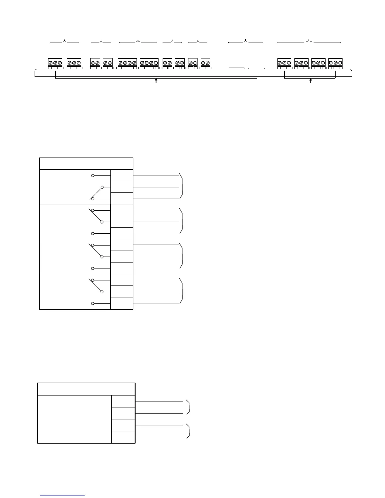
Wiring terminals located on top of main board
Status Relays
Four relays with dry contacts are provided at the upper right corner of the main board. One
relay is programmable and the trouble relay, supervisory relay and alarm relay are non-
programmable. The relay contacts are Form C and are rated for 2A@30VDC resistive.
T_
NC
T_
CO
T_
NO
Status relays
Trouble event relay
A
_NC
A_
CO
A
_NO
U
_NC
U_
CO
U_NO
S
_NC
S_
CO
S_NO
Alarm event relay
User defined relay
Supervisory event relay
Auxiliary Power Outputs Wiring
The main board provides resettable and non-resettable auxiliary power connections. The
resettable terminal interrupts the power for 5 seconds after a reset condition.
Auxiliary Power Outputs
0.75A max. @24VDC nominal
Supervised, Power Limited
X1_P
X1_N
X2_P
Auxiliary power outputs
X2_N
Resettable
Non-resettable
EARTH
S_BN
S_BP
EARTH
S_AN
S_AP
X2_P
X2_N
X1_P
X1_N
EARTH
SE_B
SE_A
GND1
EARTH
PR_B
PR_A
GND1
CT_P
CT_N
LL_SP
LL_SN
N_BP
N_BN
N_AP
N_AN
DACT
PORT1
DACT
PORT2
S_NO
S_CO
S_NC
U_NO
U_CO
U_NC
A_NO
A_CO
A_NC
T_NC
T_CO
T_NO
Power limited Non power limited
P2 device
circuit
Auxiliary power
output
Series Interface
Circuit
City tie and
lease line
NAC
DACT
Status Relays
(Shown in normal standby
condition)
2A@30VDC max. resistive
Supervised
NC – Normal closed
NO – Normal open
CO – Common
37