Do you have a question about the Siemens FC922 and is the answer not in the manual?
Provides information on accessing Desigo Fire Safety user documentation via Siemens website.
Provides information on accessing Cerberus-PRO user documentation via Siemens website.
Details safety notices, symbols, and signal words for hazard identification and avoidance.
Covers national standards, electrical installations, and general safety guidelines for product operation.
Overview of the FS20 system, its components, and capabilities for marine applications.
Lists the essential hardware components required for the FS20 panel in marine use.
Specifies suitable locations for installing FS20 equipment in marine environments.
Explains the FS20 system's software, multitasking, and initial configuration needs.
Guidelines for selecting and applying detectors based on shipboard environments and fire types.
Details areas to protect with specific detector types and best design approaches for marine spaces.
Provides guidance on installing spot-type and smoke detectors, considering environmental factors.
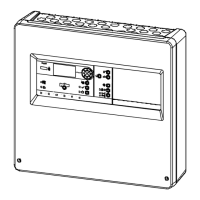
Describes the features and technical data of the marine-specific enclosure.
Step-by-step instructions for mounting the FS20 enclosure and installing components.
Identifies and labels the components on the standard operating unit board.
Details the properties and functions of the operating unit, including additional features.
Provides instructions for installing the operating unit onto the inner door.
Outlines the steps for connecting and wiring the operating unit.
Instructions on how to insert inscription strips for labeling keys and LEDs.
Provides a diagram and description of the operating unit and main board elements.
Explains the meaning and conditions for various LED indicators on the operating unit.
Describes the functions of adjustment elements like the Reset key (S32).
Lists technical specifications for supply, display, and interfaces of the operating unit.
Outlines prerequisites and safety warnings for power supply installation.
Details the recommended placement of the power supply within the enclosure.
Instructions for connecting the mains cable to the power supply unit.
Steps for installing the EMI filter to reduce noise from the power supply.
Safety notices and instructions for installing the BP-62 battery.
Procedures for wiring installation, including knockout usage and ferrite placement.
Formula and example for calculating required battery capacity.
Overview of the FCI2016-U1 periphery board's function and capabilities.
Provides a diagram of the FCI2016-U1 printed circuit board.
Configuration steps for input power and battery connections.
Overview of the FCI2017-U1 periphery board's function and capabilities.
Provides a diagram of the FCI2017-U1 printed circuit board.
Configuration steps for input power and battery connections.
Steps for installing the periphery board into the fire control panel.
Wiring and jumper configurations for notification appliance circuits.
Wiring specifications for the Bell Follower Input.
Wiring specifications and terminal block assignments for the auxiliary output.
Wiring specifications and terminal block assignments for various relays.
Wiring details for detector circuits using terminal blocks.
Functions of reset buttons for periphery board and detector circuits.
Lists technical data for supply input, battery, NAC circuit, and AUX output.
Step-by-step instructions for installing the DACT module.
Describes the communication formats supported by the DACT module.
Table showing compatible receivers and formats for the DACT.
Lists compatible alarm communicators and their technologies.
Table of event codes for various alarm types across different formats.
Instructions for installing the DIN Rail assembly and connecting wiring.
Overview of the FN2001-U1 network module's function and features.
Steps for installing the network module into the operating unit slot.
Detailed steps for fitting cable glands and installing shielding for shielded cables.
Diagram of the network module with labeled connectors and LEDs.
Pin assignments for key connectors, including SAFEDLINK wiring.
Explanation of LED indicators for network module status.
Technical specifications for the network module's supply, bus, and data rates.
Overview of the RS-485 module's features and intended use.
Instructions for installing the RS-485 module into the operating unit slots.
Diagram of the RS-485 module with labeled connectors.
Pin assignments for the X2 terminal for RS-485 interface.
Technical specifications for the RS-485 circuit, including data rates and length.
Overview of the NAC module's capabilities for class A or class B circuits.
Steps for installing the NAC module onto the periphery board.
Diagram of the NAC module with labeled connectors and jumpers.
Pin assignments for NAC 2 class A and class B circuits.
Jumper configurations for degraded mode and class A/B selection.
Technical specifications for the NAC module's supply and outputs.
Overview of the releasing module's function for activating releasing valves.
Steps for installing the releasing module onto the periphery board.
Diagram of the releasing module with labeled elements.
Pin assignments for the X5 plug connection for releasing relay output.
Explanation of LED indicators for releasing module status.
Details switches (S1, S2) and jumper (X3) for module adjustment.
Technical specifications for the releasing module's supply and output.
Overview of the remote display terminal's features and synchronization with FS20 FACP.
Step-by-step instructions for installing the remote display terminal.
Diagram of the remote display terminal's printed circuit board.
Wiring procedures for connecting the terminal to the RS-485 circuit.
Details reset key (S2) and DIP switch (S1) for terminal adjustment.
Technical specifications for the remote display terminal's supply and RS-485 circuit.
Specifies requirements for audible alarms in different marine locations.
Recommends manual stations for use with automatic detectors and their placement.
Defines smoke detectors and requirements for marine use.
Recommends spacing guidelines for smoke detectors in marine environments.
Discusses limitations for smoke detectors and recommends thermal detectors in specific areas.
Explains thermal detectors and their operating principles.
Lists approved spacing for various types of thermal detectors.
Wiring specifications for SLCs, including wire size, resistance, and capacitance.
Wiring specifications for non-addressable initiating device circuits.
Wiring specifications for local network communication circuits.
Wiring specifications for global network circuits.
Wiring specifications for NAC circuits.
Discusses power and audible alarm configurations for large systems.
Outlines system configuration for small cruise ships and zone coverage.
Safety warnings and steps for uninstalling components.
Steps to prepare the FS20 Marine Fire panel for commissioning.
Steps for panel preparation without BDV installation for commissioning.
Procedure for auto-configuring the panel via the 'Topology' menu.
Steps for auto-configuring detector circuits, including class A circuit reading.
Steps for commissioning panels using manual configuration methods.
Commissioning variant combining manual and auto-configuration steps.
Procedure for commissioning standalone panels using auto-configuration.
Steps for integrating a new panel into an existing system site.
Procedure for temporarily removing and re-inserting a device.
Procedure for temporarily removing multiple devices for maintenance.
Steps for permanently removing devices from the system.
Points to observe before updating firmware, including data backup and compatibility.
Lists system components, modules, and initiating devices for Desigo channel.
Lists system components, modules, and initiating devices for Cerberus Pro channel.
Lists common system modules, enclosures, accessories, peripherals, and devices.
Instructions for installing the required 'Siemens Sans' font for inscription display.
Steps to edit inscription strips within the document using 'Edit Picture'.
| Brand | Siemens |
|---|---|
| Number of loops | 2 |
| Display | LCD |
| Enclosure protection rating | IP30 |
| Type | Control Panel |
| Redundancy | Optional |
| Networking | Yes |
| Operating temperature range | 0 °C to +40°C |