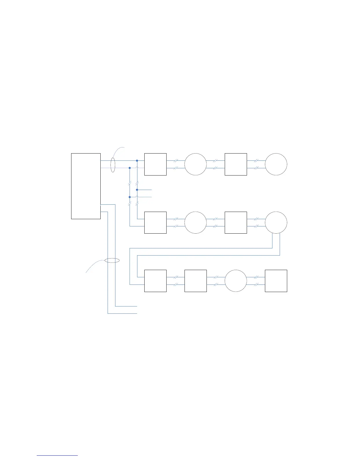
SLC Addressable Device Wiring Diagrams
Refer to the instruction sheets packed with each device.
Detectors and modules may be wired together according to several NFPA defined wiring
styles. The wiring style that is appropriate for your installation should be determined from the
relevant building codes and the local Authority Having Jurisdiction.
Style 4 wiring permits branching of circuit connections. The control equipment supervises
modules because they are active and must respond periodically to the control panel’s poll.
SLC ADDRESSABLE DEVICE CIRCUIT WIRING / OPERATION COMPARABLE TO NFPA STYLE 4
- S_AN
+ S_
AP
- S_BN
+ S_BP
ISOLATOR
MODULE
SEE NOTE
SEE
NOTE
SEE
NOTE
ISOLATOR
MODULE
SEE NOTE
SEE
NOTE
SEE
NOTE
ISOLATOR
MODULE
SEE NOTE
SEE
NOTE
SEE NOTE
TO OPTIONAL
BRANCH(
ES) OF
LOOP CIRCUIT
-
+
SUPERVISED
POWER LIMITED
SUPERVISED
POWER LIMITED
PORT-B SUPPORTS
THE SAME WIRING
AS PORT-A
-
+
PORT-A PORT-B
NOTE: Siemens SLC Devices: Detectors, Monitor Modules, or Control Modules up to a maximum of 50 devices (include both PORT-A and
PORT-B). A Maximum of 20 devices recommended per Isolator Module. A Maximum of 15 Isolator Modules per addressable device circuit.
NOTE: If more than one HCP intelligent control point module is installed on an addressable device circuit, Style 4 wiring cannot be used.
42