Do you have a question about the Siemens FC2025 and is the answer not in the manual?
Objective of the document, detailing installation and components for FS20 Marine Application.
Overview of FS20 system structures and functions.
Overview of FS20 system structures and functions.
Safety notices to protect people and property, detailing danger symbols and signal words.
Regulations for operation, including national standards and electrical installations safety.
List of standards and directives the equipment complies with.
FCC compliance statement regarding radio frequency energy and interference.
Lists minimum required hardware components for FS20 panel in marine applications.
Specifies suitable locations for FS20 panels in marine environments considering protection needs.
Describes the FS20 system's software, multitasking operation, and configuration needs.
Guidelines for selecting and applying detectors based on fire types and ambient conditions.
Details on protecting specific areas like accommodation and machinery spaces with detectors.
Considerations for installing spot-type and smoke detectors, including spacing and placement.
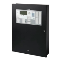
Description of the marine enclosure, its features, and technical data.
Identification and description of components on the standard operating unit.
Steps for installing the operating unit on the inner door of the enclosure.
Technical specifications for the supply input, display, and interfaces.
General steps and warnings for installing the power supply and wiring.
Guidance on the correct placement of the power supply and related components within the enclosure.
Instructions for wiring the mains cable to the power supply.
Steps for installing the EMI filter to reduce noise generated by the power supply.
Procedure and notices for installing BP-62 batteries, ensuring correct polarity and connection.
Calculation method for determining the required battery capacity based on power needs.
Function of the periphery board in supervising and controlling devices and providing power.
Jumper settings for system functions, power supply, and battery connections.
Function of the 504p periphery board for supervising devices and providing power.
Jumper settings for system functions, power supply, and battery.
Wiring diagrams for connecting notification devices as class A or class B circuits.
Overview of detector circuits, their drivers, and configuration options.
Technical specifications for supply input, battery, NAC, and AUX output.
Steps for installing the DACT module, including wiring and system connection.
Description of different communication formats supported by the DACT.
Steps to mount the DIN rail assembly onto the backbox for wiring modules.
Procedure for installing the network module into the left slot (X13).
Steps to create and configure a SAFEDLINK interface element in the Engineering Tool.
Technical specifications for the supply, system bus, and data rate of the network module.
Function of the RS-485 module for periphery devices and its features.
Procedure for installing the RS-485 module into specified slots in the operating unit.
Pin assignments for Plug X2, the RS-485 interface terminal.
Steps for installing the NAC module onto the periphery board and connecting it.
Jumper settings for degraded mode and class A/B selection for NAC 2 circuits.
Technical specifications for the NAC module's supply, outputs, and supervised parameters.
Steps for installing the releasing module onto the periphery board.
Switches and jumper settings for arming/disarming outputs and degraded mode.
Technical specifications for the releasing module, including voltage, current, and dimensions.
Steps for installing the remote display terminal enclosure and back box.
Wiring diagrams for connecting the remote terminal to the RS-485 circuit.
Details on the reset key and DIP switch settings for baud rate and device address.
Requirements for sounding audible alarms in specific locations and general alarm activation.
Recommendation and placement guidelines for manual stations in fire detection systems.
Definition of smoke detectors and marine detector requirements.
Explanation of thermal detectors and their operating principles.
Maximum approved spacing for different types of thermal detectors.
Wiring specifications for SLCs, including wire size, resistance, and capacitance.
Wiring specifications for non-addressable circuits, including wire size and resistance.
System configuration example for large FS20 systems complying with SOLAS and USCG.
Procedure for uninstalling components, including safety warnings for electrical voltage.
Steps to prepare the FS20 Marine fire panel for commissioning, including connections and startup.
Procedure for auto-configuring the panel via the 'Topology' menu.
Process for commissioning panels using manual configuration methods.
Procedure for temporarily removing and re-inserting a device for servicing.
Procedure for permanently removing devices from the system and configuration.
Points to observe before updating firmware, including data backup and compatibility.
List of system components, modules, and initiating devices for the Desigo channel.
List of system components, modules, and initiating devices for the Cerberus Pro channel.
Lists common system modules, enclosure, and accessories.
Checklist for installation personnel covering components and tasks.
Instructions for installing the required 'Siemens Sans' font for system operating units.
Guide on how to edit inscription strips within the document figures.
Example display of LED indicators for the FCM2019-U1 module.
Definitions of acronyms and terms used throughout the document.
| Model | FC2025 |
|---|---|
| Manufacturer | Siemens |
| Storage Temperature | -20°C to +60°C |
| Protection Class | IP30 |
| Loops | 2 |
| Mounting Type | Wall-mounted |
| Type | Control Panel |
| Humidity | Up to 95% RH, non-condensing |
| Communication Interface | RS-485 |
| Display | LCD |
| Keys | Membrane keypad |