27
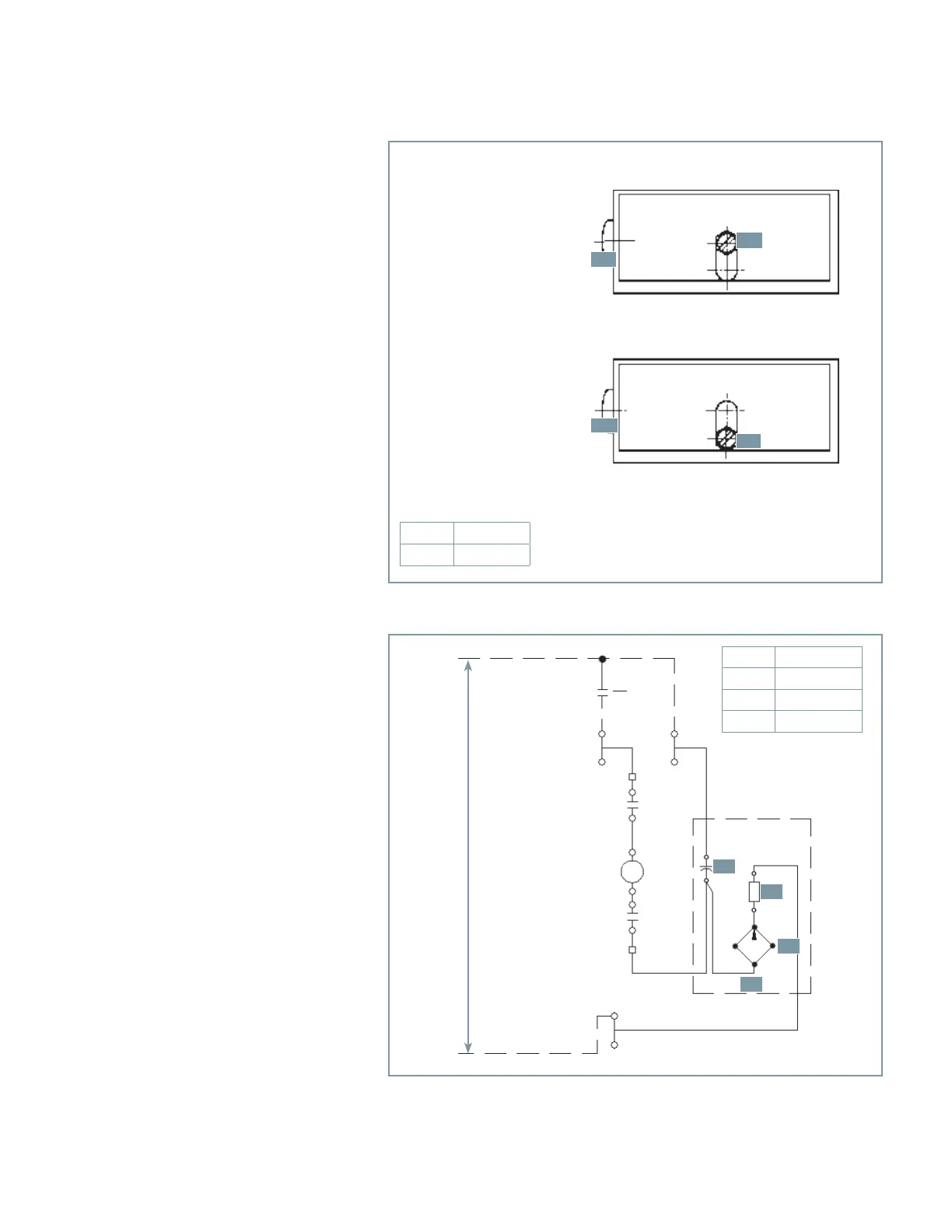
Figure 21: Undervoltage lock/operate selection
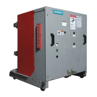
Figure 22: Capacitor-trip device
Position A: locked
Position B: unlocked (operating position)
Cancel the lock for the undervoltage release by shifting the locking screw (29.0) from A to B.
A
B
A
B
120 or 240 Vac
supply
01
T
24
23
52o
SD5
34
33
52o
A1
A2
52T
(+)
(-)
(+)
(-)
1
2
Construction and mode of operation of
secondary release and undervoltage
release
Refer to Figure 19: Construction of secondary
shunt release and Figure 20: Latch details on
page 26 and Figure 21: Undervoltage lock/
operate selection.
The release consists of a spring power-storing
mechanism, a latching device and an
electromagnet. These elements are
accommodated side-by-side in a housing
(3.0), with a detachable cover and three
through-holes (5.0) for fastening screws. The
supply leads for the trip coil are connected to
a terminal block (33.0).
The energy-storing mechanism consists of the
striker pin (23.0) and its operating spring
(31.0), which is mostly located inside the
striker pin (23.0). When the spring is
compressed, the striker pin is held by a latch
(25.0), whose sloping face is forced against
the appropriately shaped striker pin (23.0) by
spring (27.0). The other end of the latch
(25.0) is supported by a partly-milled locking
pin (21.0) (refer to Figure 20: Latch details on
page 25) that pivots in the cover sheets of the
magnet armature (9.0). The armature (9.0)
pivots in front of the poles of the U-shaped
magnet core, (1.0) and is pulled away from it
by the tension spring (11.0).
If the magnet coil (7.0) of the shunt release
3AX1101 is energized by a trip signal, or if
the tripping pin (15.0) is mechanically
actuated, magnet armature (9.0) is swung
against the pole faces.
When this happens, the latch (25.0) loses its
support and releases the striker pin (23.0),
that is forced out by the spring (31.0).
On the undervoltage release 3AX1103, the
latch (25.0) is held by the locking pin (21.0)
as long as the armature (9.0) is attracted
(energized) (refer to Figure 17: Operator
sequence operation diagram on page 24). If
the circuit of the magnet coil (7.0) is
interrupted, the armature (9.0) drops off,
thus causing the latch (25) to lose its support
and release the striker pin (23).
23.0
Striker pin
29.0
Screw
23.0
29.0
23.0
29.0
A
Capacitor
B
Resistor
C
Rectifier
D
Capacitor trip
A
B
C
D