Do you have a question about the Siemens GMI Series and is the answer not in the manual?
Defines who is qualified to work on the equipment and the hazards involved.
Explains signal word definitions (Danger, Warning, Caution) and critical safety procedures.
Information on obtaining professional technical guidance and advisory assistance from Siemens.
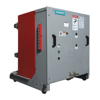
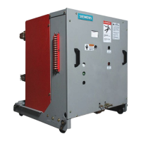
Details procedures for inspecting, receiving, and safely handling the circuit breaker.
Provides guidance on proper indoor and outdoor storage conditions and space heating.
Covers inspections, checks, and tests without control power, including spring discharge.
Details steps for removing the circuit breaker from lower and upper cells.
Explains the function and construction of vacuum interrupters and primary disconnects.
Describes the stored energy mechanism, its components, and its trip-free operation.
Explains the different operational modes like charging, closing, tripping, and auto-reclosing.
Details spring charging motor, solenoids, secondary disconnect, and anti-pump relay.
Describes auxiliary, MOC, and TOC switches used for control and status indication.
Explains limit switches and optional capacitor trip devices.
Covers the undervoltage release feature and essential operating interlocks.
Outlines recommended maintenance intervals, service conditions, and necessary hand tools.
Covers essential maintenance tasks including primary path checks, operator mechanism, and electrical controls.
Details high-potential tests for vacuum integrity, insulation, and contact resistance.
Lists recommended overhaul schedules based on closing operations and identifies key components for replacement.
Provides procedures for replacing critical components like springs, solenoids, and vacuum interrupters.
Addresses problems related to the breaker failing to close or trip, listing symptoms and possible causes.
Covers nuisance or false closing and tripping issues, detailing electrical and mechanical problems.
Provides tables with circuit breaker ratings, control data, auxiliary switch capacities, and weights.
| Poles | 1P, 2P, 3P, 4P |
|---|---|
| Tripping Characteristics | B, C, D |
| Terminal Type | Screw Terminals |
| Breaking Capacity | 6 kA |
| Standards | IEC/EN 60898-1 |
| Mounting | DIN Rail |