EasyManua.ls Logo

Siemens ETU776 User Manual

Siemens ETU776
56 pages
To Next Page IconTo Next Page
Page #1 background imageLoading...
Page #1 background image
Circuit Breaker Accessory
Zubehör für Leistungsschalter
Electronic Trip Unit Models 755 - 776
Überstromauslöser Spezialsortiment 755 - 776
Catalog No. / Bestell-Nr.: 11-C-9010-01
HINWEIS NOTICE
Das Zubehör ist verwendbar für die folgenden Geräte vom Siemens
Typ WL leistungsschalter:
Leistungsschalter (E231263)
Leistungsschalter (E223684)
Leistungsschalter mit integrierten Sicherungen (E224354)
This accessory is intended for use with the following Siemens type
WL circuit breakers:
Molded Case Circuit Breaker (E231263)
Low Voltage AC Power Circuit Breaker (E223684)
Low Voltage AC Integrally Fused Power Circuit Breaker (E224354)
GEFAHR DANGER
Gerät steht während der Arbeiten unter gefährlicher elek-
trischer Spannung.
Kann Tod, schwere Personenschäden sowie Schäden an
Geräten und Ausrüstung bewirken.
Vor Beginn der Arbeiten an diesem Niederspannungs-Schalt-
gerät oder an der Niederspannungs-Schaltanlage sind unbe-
dingt alle primären und sekundären Stromkreise
spannungsfreizuschalten. Sicherheitsbestimmunger der OSHA
(lock-out / tag-out policies) sind streng einzuhalten.
Nur qualifiziertes Personal darf an dem Gerät arbeiten, wel-
ches mit Warn-, Sicherheitshinweisen und Wartungsvorschrif-
ten vertraut gemacht wurde.
Die erfolgreiche und sichere Funktion dieses Gerätes hängt
von ordentlicher Bedienung, Installation, Behandlung und War-
tung ab.
Nur original SIEMENS Zubehör sowie original SIEMENS
Ersatzteile dürfen an diesem Gerät eingebaut werden
Alle hier aufgeführten Bestimmungen für Wartung und Inspek-
tionen müssen streng eingehalten werden.
Hazardous voltages are present during operation.
Will cause death, serious personal injury, or equipment/
property damage.
Disconnect power before performing service or retrofitting on
Low Voltage Switchgear or Low Voltage Power Circuit Brea-
kers, strictly adhering to OSHA lock-out / tag-out policies.
Only qualified personnel should work on this equipment, after
becoming thoroughly familiar with all warnings, safety notices,
and maintenance procedures contained herein and on the
devices.
The successful and safe operation of this equipment is depen-
dent on proper handling, installation, operation, and mainte-
nance.
Only SIEMENS authorized repair or replacement parts shall be
used on this equipment.
All maintenance / inspection policies dictated here-within must
be strictly adhered to.
s

Other manuals for Siemens ETU776

Question and Answer IconNeed help?

Do you have a question about the Siemens ETU776 and is the answer not in the manual?

Siemens ETU776 Specifications

General IconGeneral
BrandSiemens
ModelETU776
CategoryCircuit breakers
LanguageEnglish

Summary

Circuit Breaker Accessory Guide

Accessory Notice and Safety Warnings

Provides general notices, hazard warnings (DANGER/GEFAHR), and essential safety precautions.

Symbols and Document Information

Document Symbols Explained

Explains symbols used throughout the documentation.

ETU755 Trip Unit Overview

ETU755 Ansicht and Design Details

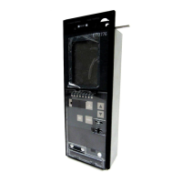
Detailed view and design elements of the ETU755 trip unit.

ETU755 Safety Cautions

Important safety warnings and cautions for operating the ETU755 trip unit.

Overcurrent Protection Settings

Vorsicht for Overcurrent Settings Adjustment

Cautionary advice for adjusting overcurrent protection settings.

Overcurrent Protective Functions Explained

Lists available protective functions for overcurrent protection.

Overcurrent Protection Characteristics

L-Auslösung Characteristics

Characteristics for overload protection (L-tripping).

S-Auslösung Characteristics

Characteristics for short-time delay short-circuit tripping.

I-Auslösung Characteristics

Characteristics for instantaneous short-circuit tripping.

Erdschlussauslösung Characteristics

Characteristics for ground-fault tripping.

ETU776 Trip Unit Overview

ETU776 Ansicht and Design Details

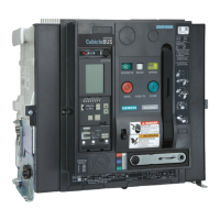
Detailed view and design elements of the ETU776 trip unit.

ETU776 Safety Cautions

Important safety warnings and cautions for operating the ETU776 trip unit.

ETU776 Overcurrent Protection Settings

Vorsicht for ETU776 Overcurrent Settings

Cautionary advice for adjusting ETU776 overcurrent protection settings.

ETU776 Overcurrent Protective Functions

Lists protective functions for ETU776 overcurrent protection.

ETU776 Overcurrent Characteristics

Characteristics applicable to ETU776 overcurrent protection.

Trip Unit Indicators and Status

Activation, Alarm, and Communication Indicators

Displays for trip unit activation, overcurrent alarm, and communication status.

Extended Protective Function Status

Indicates if an extended protective function has tripped.

Protective Function Status and Errors

Tripped Protective Function Indicators

Shows which protective function has tripped and its cause.

T.U. ERROR LED Status Explanation

Explains the meaning of T.U. ERROR LED flashes or permanent light.

Detailed Protective Functions

Basic Protective Functions Overview

Details on basic protective functions ensuring operation without auxiliary voltage.

Overload Protection L-Tripping Settings

Settings and characteristics for overload protection (L-tripping).

Short-time Delay Short-circuit S-Tripping Details

Details on short-time delay short-circuit protection (S-tripping).

Advanced Protective Functions

Instantaneous Short-circuit I-Tripping Details

Details on instantaneous short-circuit protection (I-tripping).

Ground-fault Tripping G-Tripping Details

Details on ground-fault protection (G-tripping).

Neutral Conductor Protection Settings

N-Tripping Settings and Caution

Settings and cautions for neutral conductor overload protection.

Additional Trip Unit Functions

Load Monitoring Functionality

Functionality for monitoring and signaling load changes.

Leading Signal L-Tripping Function

Provides a pre-trip warning signal for overload conditions.

Phase Failure Protection Operation

Protection against phase loss, with automatic setting adjustment.

Thermal Memory Control

Ability to continue thermal process simulation without external power.

Advanced Protection Features and Selectivity

Zone Selective Interlocking (ZSI) Functionality

Enables precise localization of short-circuits in multi-level systems.

I⁴t Overload Protection Selectivity

Improves overload protection selectivity with fuses using I⁴t characteristic.

Switching Off Overload Protection

Option to disable overload protection, e.g., for generator supply.

Protection Switching Capabilities

I²t Short-circuit Protection Switching

Allows switching to I²t characteristic for better selectivity with downstream fuses.

Changeable Parameter Sets Functionality

Allows storing and switching between two parameter sets.

I²t Ground-fault Protection Switching

Enables I²t characteristic for improved ground-fault protection selectivity.

Parameter Display and Data Information

Displayed Technical Data and Units

Lists parameters and their corresponding units and changed data.

Parameter Change Mode Button Functions

Explains button actions when viewing parameter changes.

Graphical Display Interface

Graphical Display Features and Operation

Description of the fixed-mounted graphical display and its capabilities.

Display Design Elements Explained

Breakdown of the display's components like menu title, lines, and status.

Display Status and Operational Screens

Understanding the Status Line

Indicates operator actions and active settings via bold symbols.

Interpreting Bar Diagram Displays

Displays measured values numerically and graphically as bar diagrams.

Display During Operation Mode

Shows operational screen with currents, including background dimming.

Menu Navigation and Operation

Accessing the Main Menu Structure

Procedure for polling and accessing the main menu.

Navigating Menu Structure with Buttons

How to use operating keys to navigate through the menu structure.

Selecting Menu Items

How to select a menu item using the operating keys.

Displaying Measured Values: Currents and Frequency

Displaying Current Measurements (Example 1)

How to display current measurements, including min/max values.

Displaying Frequency Measurements (Example 2)

How to display frequency measurements, including THD and UTHD.

Displaying Measured Values: Harmonics

Displaying Harmonic Content (Example 3)

How to display harmonic content of voltage and current.

Displaying Measured Values: Power and Protection Settings

Displaying Power Measurements (Example 4)

How to display active, reactive, and apparent power, and average power.

Displaying Protection Parameter Settings (Example 5)

How to view configured protection parameters for different trip types.

Querying Maintenance and Diagnostic Information

Querying Maintenance Information (Example 6)

Accessing maintenance logs like total operations and trip counts.

Adjusting Characteristic Display Settings

Setting Curve Representation (Example 7)

How to configure the display of trip event curves.

Setting Trigger Events for Characteristics

Setting Trigger A Configuration

Configuration options for Trigger A event settings.

Selecting Events for Characteristic Display

Selecting Events for Display (Example 8)

Process for choosing events to display as characteristics.

Displaying Waveforms and Event Data

Displaying Waveform Data

How to view waveform data for selected events.

Displaying Event Details

Accessing and displaying event details.

Displaying Recorded Characteristics

Displaying Characteristics (Example 9)

How to view recorded characteristic curves.

Waveform Display Options

Waveform Display Variations

Various ways to display waveform data.

Parameter and Password Management

Setting Protection Parameters (Example 10)

How to set specific protection parameters.

Entering and Changing Password (Example 11)

Procedure for entering or changing the password.

Password and Parameter Saving Procedures

Saving Parameter Changes Confirmation

Confirming whether to save parameter changes.

New Password Entry Process

Process for entering a new password.

Identification and Reset Functions

Identification Display (Example 12)

How to display trip unit identification details.

Resetting Max/Min Values (Example 13)

Procedure for resetting maximum and minimum measured values.

Displaying Measured Values: Currents and Frequency (English)

Displaying Current Measurements in English (Example 1)

How to display current measurements in English.

Displaying Frequency Measurements in English (Example 2)

How to display frequency measurements in English.

Displaying Measured Values: Harmonics (English)

Displaying Harmonic Content in English (Example 3)

How to display harmonic content in English.

Displaying Measured Values: Power and Protection Settings (English)

Displaying Power Measurements in English (Example 4)

How to display power measurements in English.

Displaying Protection Parameters in English (Example 5)

How to view protection parameters in English.

Querying Maintenance Information (English)

Querying Maintenance Information in English (Example 6)

Accessing maintenance logs in English.

Adjusting Characteristic Representation (English)

Setting Characteristic Representation in English (Example 7)

How to configure characteristic display in English.

Setting Trigger Events (English)

Setting Trigger A Configuration in English

Configuration options for Trigger A in English.

Selecting Events for Display (English)

Selecting Events for Display in English (Example 8)

Process for choosing events to display in English.

Displaying Waveforms and Events (English)

Displaying Waveform Data in English

How to view waveform data in English.

Displaying Event Details in English

Accessing and displaying event details in English.

Displaying Recorded Characteristics (English)

Displaying Characteristics in English (Example 9)

How to view recorded characteristic curves in English.

Waveform Display Options (English)

Waveform Display Variations in English

Various ways to display waveform data in English.

Parameter and Password Management (English)

Setting Protection Parameters in English (Example 10)

How to set protection parameters in English.

Entering and Changing Password in English (Example 11)

Procedure for entering or changing the password in English.

Password and Parameter Saving Procedures (English)

Saving Parameter Changes Confirmation in English

Confirming parameter changes in English.

New Password Entry Process in English

Process for entering a new password in English.

Identification and Reset Functions (English)

Identification Display in English (Example 12)

How to display trip unit identification in English.

Resetting Max/Min Values in English (Example 13)

Procedure for resetting maximum and minimum measured values in English.

Rating Plug Information

Rating Plug Definition and Error Handling

Explains the role of the rating plug and errors related to its use.

Rating Plug Order Numbers by Frame Size

Lists order numbers for rating plugs based on frame size.

Ground-Fault Protection Modules

Ground-Fault Module Installation and Removal

Instructions for installing and removing ground-fault protection modules.

Ground-Fault Protection Module Types and Capabilities

Details on different ground-fault protection module versions and their capabilities.

Ground Fault Module Communication and Configuration

GFM A 755-776 Module Signals and Programming

How alarm/trip signals are transmitted and module programmability.

GFM AT 755-776 Ground Fault Configuration

Configuration for ground fault protection, including detection methods.

Field Installing Modules

Removing Dummy Module Procedure

Steps for removing a dummy module.

Installing Ground-Fault Protection Module

Instructions for installing and latching the ground-fault protection module.

Ground Fault Module and Trip Unit Replacement

Ground Fault Module Installation Steps

Steps for installing the ground fault module, including connection and testing.

Ground-Fault Protection Module Order Numbers

Lists order numbers for ground-fault protection modules.

Trip Unit Replacement Procedure

Safety precautions and steps for replacing the trip unit.

Trip Unit Removal and Installation Process

Trip Unit Removal Guide

Step-by-step guide for removing the trip unit.

Connector Disconnection Instructions

Instructions for disconnecting electrical connectors.

Trip Unit Installation and Ordering Information

Trip Unit Installation Guide

Instructions for installing the trip unit in reverse order.

Ordering Trip Unit Systems and Type Labels

Guidance on ordering trip unit systems and updating type labels.

Internal Self-Test of Overcurrent Tripping Function

Self-Test Conditions and Interruption Methods

Prerequisites for the self-test and how to interrupt it.

Interpreting Running Light and Test Results

Interpretation of the running light sequence and test outcomes.

Internal Self-Test with Tripping Function

Self-Test with Tripping Conditions and Interruption

Conditions for performing self-test with tripping and interruption methods.

Running Light and Test Outcome Interpretation

Interpretation of running light and test results for self-test with tripping.

Procedures for Re-closing After Tripping

Procedures for re-closing a circuit breaker after a trip.

Sealing and Locking Device Procedures

Sealing and Locking Device Application

Steps for applying the sealing and locking device.

Sealing Wire Length Recommendation

Notice regarding the length of the sealing wire.

Sealing Device Order Numbers

Order numbers for sealing devices for ETU755 and ETU776.

Related product manuals