Do you have a question about the Siemens ETU755 and is the answer not in the manual?
Lists compatible Siemens WL type circuit breakers for the accessory.
Warns about dangerous voltage and potential hazards during work.
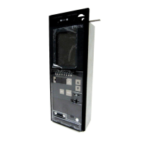
Shows the front panel view of the ETU755 circuit breaker.
Details the design elements and features of the ETU755 circuit breaker.
Instructions for protecting electrostatic sensitive devices (ESD) during handling.
Warns about adjusting parameters only when the circuit breaker is OPEN.
Lists methods and overview of protective functions for parameter adjustment.
Shows setting ranges for overload and short-time delay short-circuit tripping curves.
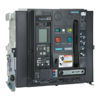
Shows the front panel view of the ETU776 circuit breaker.
Details the design elements and features of the ETU776 circuit breaker.
Instructions for protecting electrostatic sensitive devices (ESD) during handling.
Explains indications for trip unit activation and overcurrent alarms.
Details indications for communication status and tripped extended functions.
How the trip status is indicated via LEDs and buttons.
Explains the meaning and causes of flashing or permanently lit T.U. ERROR LEDs.
Basic functions, r.m.s. current calculation, and overload protection settings (IR, tr).
Explains Isd and tsd for selectivity in short-circuit protection.
Describes protection against high ground-fault currents using Ig and tg settings.
Covers overload protection for the neutral conductor using IN and tr settings.
Monitors load, generates signals, and provides advance overload warning.
Phase failure protection and continuation of thermal process simulation.
Allows precise localization of short-circuits in multi-level systems.
Switchable I4t overload protection and disabling overload protection.
Allows storing and switching between two different parameter sets for protective functions.
Lists displayed technical data and their corresponding units for ground fault.
Explains button functions when viewing parameter changes.
Describes the structure of the graphical display, including menu title, lines, and status.
Explains symbols in the status line indicating operator actions and active settings.
Describes bar diagrams for measured values and display during operation.
Explains how to access and navigate through the main menu structure.
Explains how to select menu items using the device buttons.
Shows how to display current values (L1, L2, L3, N) and related statistics.
Demonstrates displaying frequency, THD, UTHD, Form F, and Crest F.
Illustrates how to view harmonic data, including THD and individual harmonic percentages.
Shows how to display active power (P, PL1, PL2, PL3, Pavg) and related values.
Demonstrates how to view configured protection parameters for different trip types.
Shows how to access maintenance information like total operations and trip logs.
Guides through setting up triggers and displaying characteristic curves.
Shows how to select events (like currents or events A/B) for characteristic display.
Demonstrates how to display recorded curves for selected events.
Guides through setting various protection parameters like trip levels and delays.
Explains how to enter or change the password for system access.
Shows how to display trip unit identification details like serial number and user comment.
Guides through resetting the minimum and maximum measured value buffers.
Explains that the rating plug defines the rated continuous current and its role.
Describes error handling and provides a table of rating plugs and order numbers.
Warns about removing the rating plug only when the circuit breaker is open.
Explains module functions, combinations, and detection methods.
Describes the GFM A module's alarm-only function and programmability.
Details the GFM AT module's protection function, programmability, and detection modes.
Illustrates the procedure for removing a dummy module.
Shows the steps for installing and latching a ground-fault protection module.
Lists key steps and safety precautions for replacing the trip unit.
Provides guidance on ordering trip units and updating the type label for new configurations.
Details the process of removing connectors and circuit breaker parts for trip unit access.
Covers reverse installation, mandatory testing, and ordering trip units.
Notes on updating type labels and contacting support for configuration issues.
Outlines conditions, running light sequence, LED indications, and test outcomes for the internal self-test.
Illustrates sealing steps and lists order numbers for related kits.
| Brand | Siemens |
|---|---|
| Model | ETU755 |
| Category | Circuit breakers |
| Language | English |