10
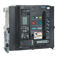
Schutzfunktionen
Grundschutzfunktionen
Die Grundschutzfunktionen des Überstromauslösers sind ohne
zusätzliche Hilfsspannung sichergestellt. Die erforderliche Energie
wird von schalterinternen Energiewandlern bereitgestellt.
Für die Bewertung der Ströme wird durch die Elektronik des Über-
stromauslösers der Effektivwert (r.m.s.) berechnet.
Die Parametrierung der einzelnen Funktionen erfolgt typenabhängig
mittels:
- elektronischer Datenübertragung (ETU755 - 776) über:
- den BDA
- den PROFIBUS-DP / MODBUS
- Bedientastenfeld (ETU776).
Überlastschutz – L-Auslösung
Der Einstellwert I
R
bestimmt den maximalen Dauerstrom, bei dem
der Schalter ohne Auslösung betrieben werden kann. Der Träg-
heitsgrad t
R
bestimmt, wie lange eine Überlast andauern kann,
ohne dass es zu einer Auslösung kommt.
Die Auslösekennlinie hat eine I
2
t-Charakteristik. Für einige Über-
stromauslöser besteht die Möglichkeit, auf eine I
4
t-Charakteristik
umzuschalten.
Kurzverzögerte Kurzschlussauslösung – S-Auslösung
Bei den Überstromauslösern ETU755 - ETU776 kann die Auslö-
sung infolge eines Kurzschlussstromes I
sd
um die Zeit t
sd
verzögert
werden.
Damit kann eine Selektivität des Kurzschlussschutzes in Schaltan-
lagen mit mehreren Staffelebenen erreicht werden.
1)
Die Verzögerungszeit 0,02 s ist keine Staffelzeit!
In dieser Stellung wird die Motorschutzfunktion eingeschaltet.
2)
Für Einstellwerte t
sd
> 0,4 s erfolgt automatisch eine Reduzierung des maximal
möglichen Einstellwertes I
sd
in Abhängigkeit von der Baugröße auf:
BG II : 20 kA
BG III : 30 kA
Die Einstellung „OFF“ für die Überstromauslöser ETU755 und
ETU776 dient dazu, den kurzverzögerten Kurzschlussschutz abzu-
schalten.
Bei Verwendung der zeitverkürzten Selektivitätssteuerung (ZSI)
wird der eingestellte Wert für die Verzögerungszeit t
sd
außer Kraft
gesetzt. Erhält der Leistungsschalter im Auslösefall kein Blockiersi-
Einstellwerte für I
R
ETU755 - 776 I
R
= (0,4 - 1,0) x I
n
(Angabe in Ampere)
Einstellwerte für t
R
ETU755 - 776 t
R
= 2 - 30 s (bei 6 x I
R
)
Einstellwerte für I
sd
ETU755 - 776
I
sd
= 1,25 x I
n
- 0,8 x I
CW
(Angabe in Ampere)
Einstellwerte für t
sd
ETU755 - 776 t
sd
= 0,02(M)
1)
/ 0,08 - 4 s
2)
; OFF
Protective functions
Basic protective functions
The basic protective functions of the trip unit are ensured without
additional auxiliary voltage. The required power is supplied by inter-
nal transformers of the circuit breaker.
To evaluate the currents, the electronic system of the trip unit calcu-
lates the r.m.s value.
The individual functions are parameterized according to the types
via:
- electronic data transfer (ETU755 - 776) via:
- the test socket with the BDA
- the PROFIBUS-DP / MODBUS
- the control board (ETU776)
Overload protection – L-tripping
The current setting I
R
defines the maximum continuous current the
circuit breaker can carry without tripping. The long time delay t
R
determines the maximum duration of an overload without tripping.
The tripping characteristic is an I
2
t characteristic. Some trip units
can be switched over to an I
4
t characteristic.
Short-time-delay short-circuit tripping – S-tripping
On trip units ETU755 - 776, tripping due to the short-circuit current
I
sd
can be delayed by the time t
sd
.
This provides selectivity for the short-circuit protection in switchgear
with several grading levels.
1)
The time delay 0.02 sec. is not a grading time!
The motor protection function is activated in this position.
2)
For settings t
sd
>0.4 sec., the maximum possible setting I
sd
is reduced automa-
tically according to the frame size:
Frame size II : 20 kA
Frame size III : 30 kA
The setting "OFF" for the trip units ETU755 and ETU776 is provided
to deactivate the short-time-delay short-circuit protection.
If the zone selective interlocking (ZSI) is used, however, the setting
for the time delay t
sd
is deactivated. If the circuit breaker does not
receive any blocking signal from a downstream circuit breaker, it will
Current settings for I
R
ETU755 - 776 I
R
= (0.4 - 1.0) x I
n
(data in Amps)
Settings for t
R
ETU755 - 776 t
R
= 2 - 30 sec. (at 6 x I
R
)
Current settings for I
sd
ETU755 - 776
I
sd
= 1.25 x I
n
- 0.8 x I
CW
(data in Amps)
Settings for t
sd
ETU755 - 776 t
sd
= 0.02(M)
1)
/ 0.08 - 4 sec.
2)
; OFF
 Loading...