Installation checks and functional tests
3. Depress and hold down the circuit
breaker racking latch release handle
and pull the circuit breaker out from
the DISCONNECT position. The circuit
breaker can now be removed from the
cubicle.
4. The circuit breaker is now free to be
rolled out onto the floor using the
handles on the front. The wheels of the
circuit breaker are at floor level (unless
the switchgear is installed on a raised
pad), and one person can handle the
unit.
Removal from cell in outdoor non-walk-
in enclosures or for indoor switchgear
installed on a raised pad
Removal of the circuit breaker from a non-
walk-in outdoor-switchgear assembly is
similar to removal of a circuit breaker at
floor level with several additional steps.
The procedure for removal of a circuit
breaker not located at floor level is:
1. If the circuit breaker is in the
DISCONNECT position, skip to step 4.
Close the circuit breaker compartment
door and secure all latches.
2. Insert the racking crank onto the
racking screw on the front of the circuit
breaker cell, and push in (refer to
"Racking crank engagement procedure"
on page 11). This action operates the
racking-interlock latch.
For arc-resistant type GM-SG-AR
switchgear, rotate the racking access
cover to enable insertion of the racking
crank.
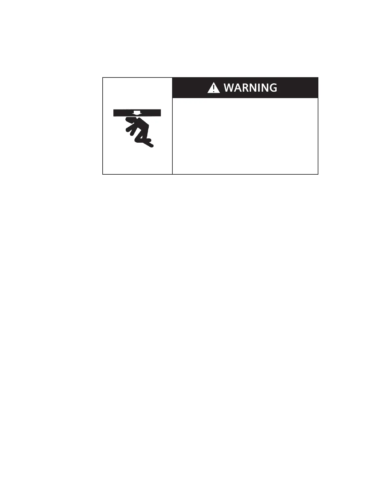
Heavy weight.
Can result in death, serious injury or property damage.
Observe all handling instructions in this instruction manual to
prevent tipping or dropping of equipment.
Removal from cell in indoor switchgear
if not on raised pad and Shelter-Clad
outdoor switchgear
After performing the spring discharge
check (with control power de-energized),
remove the circuit breaker from its
switchgear cubicle.
1. Insert the racking crank on the racking
screw on the front of the circuit
breaker cell, and push in (refer to
"Racking crank engagement procedure"
on page 11). This action operates the
racking-interlock latch. Figure 2: Type
GMSG vacuum circuit breaker racking
on page 11 shows circuit breaker
racking.
For arc-resistant type GM-SG-AR
switchgear, rotate the racking access
cover to enable insertion of the racking
crank.
2. Rotate the racking crank
counterclockwise until the circuit
breaker is in the DISCONNECT position,
as indicated on the racking
mechanism.
Open the circuit breaker compartment
door. For arc-resistant type GM-SG-AR
switchgear, slide the covers to the side
that allows the circuit breaker to rollout
of the cell.
10
 Loading...