Vacuum interrupter/operator
Figure 11: Type GMSG vacuum circuit breaker
20.0
40.0
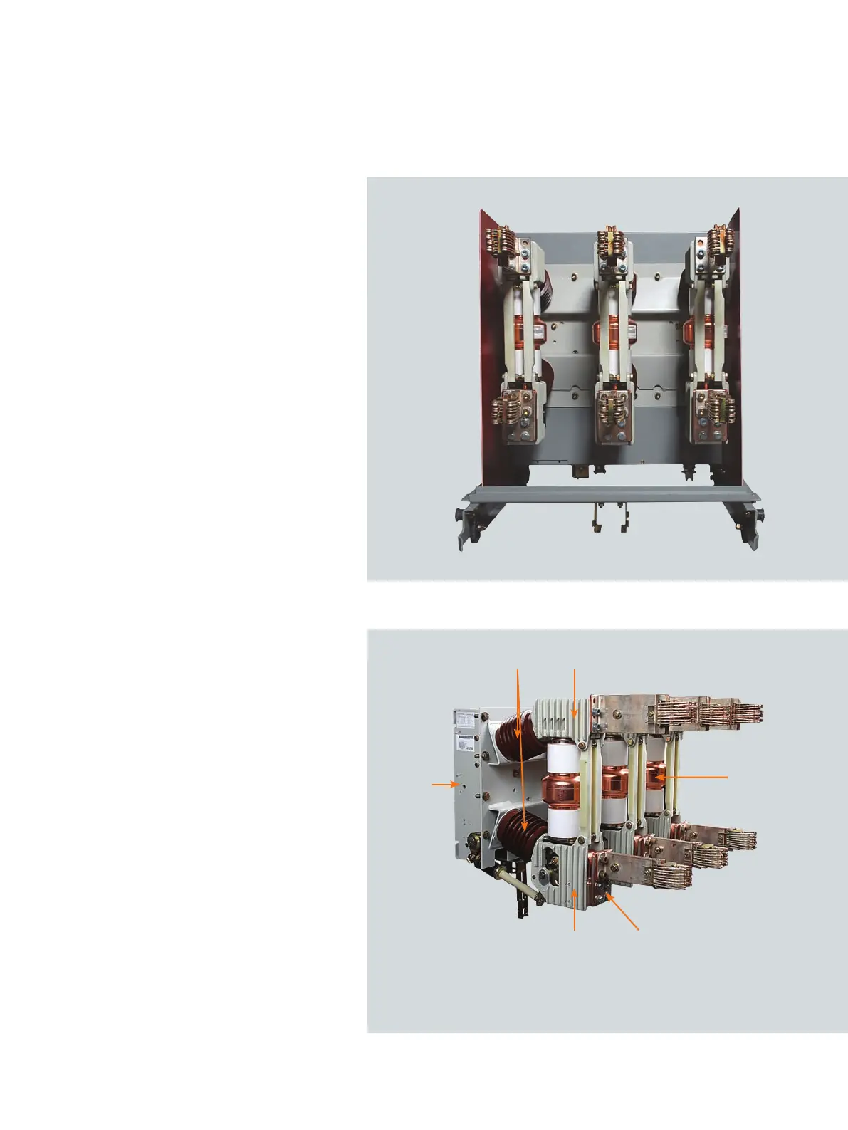
Figure 12: Interrupter/operating mechanism module
16.0 - Insulator
20.0 - Pole head
29.0 - Lower connection terminal
30.0 - Vacuum interrupter
40.0 - Pole bottom
60.0 - Operator housing
60.0
16.0
30.0
29.0
Construction
Refer to Figure 12: Interrupting/operating
mechanism module on page 17, Figure 13:
Operating mechanism controls and
indicators on page 18, Figure 14: Type
GMSG vacuum circuit breaker pole section
on page 19 and Figure 15: Stored-energy
operating mechanism on page 20.
Each of the circuit breaker poles is fixed to
the rear of the operating-mechanism
housing (60.0) by cast-resin insulators
(16.0).
The insulators also connect to the upper
(20.0) and lower (40.0) pole-supports that
in turn support the ends of the vacuum
interrupter (30.0). Primary stud-extensions
are attached directly to the upper pole-
support (20.0) and lower terminal (29.0).
The energy-storing mechanism and all the
control and actuating devices are installed
in the mechanism housing (60.0).
The mechanism is of the spring-stored
energy-type and is mechanically and
electrically trip-free.
The OPEN/CLOSED indicator (58.0),
CHARGED/DISCHARGED indicator (55.0)
and the operations counter (59.0) are
located on the front of the mechanism
housing (60.0).
Shown with outer-phase
barriers removed
Shown with outer-phase barriers installed
17