Vacuum interrupter/operator
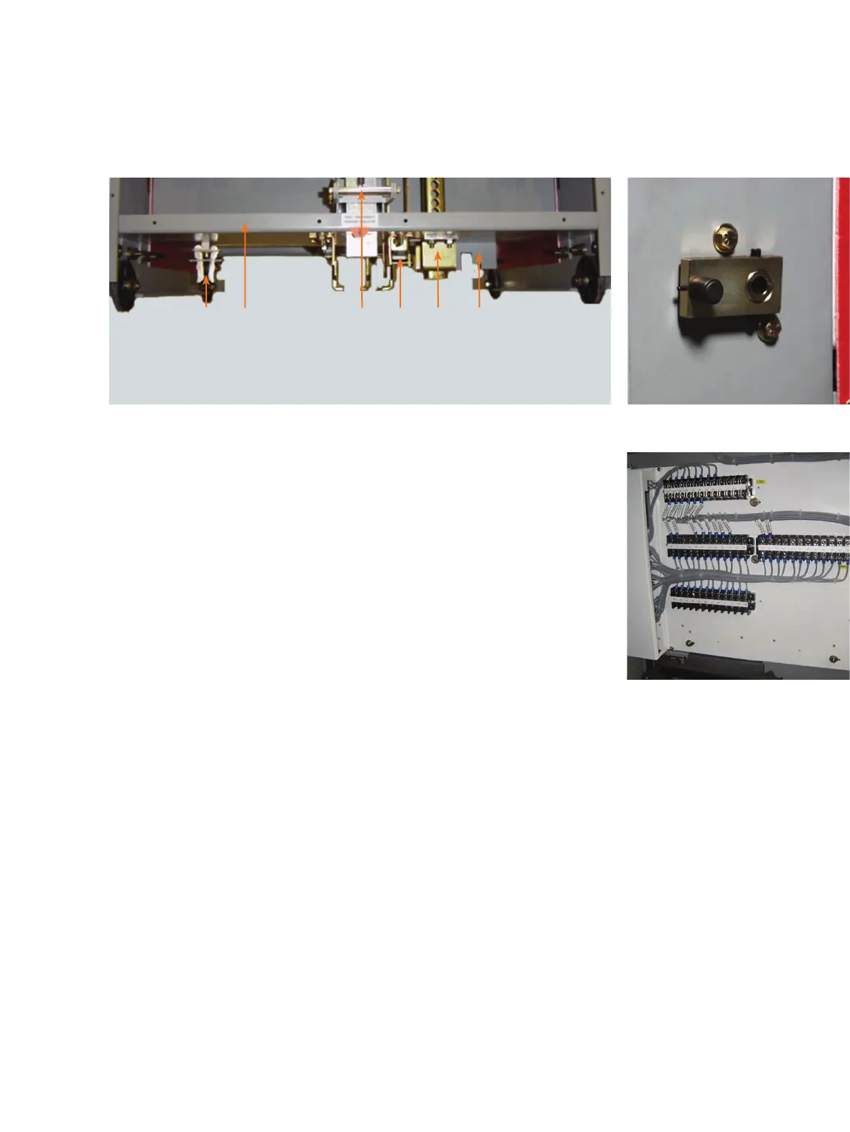
Figure 26: MOC switch operating
arm on a circuit breaker
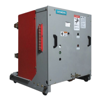
Figure 27: MOC (bottom) and TOC
(top) switches and associated
terminal blocks
Mechanism-operated cell (MOC) switch
(optional)
Figure 26: MOC switch operating arm on a
circuit breaker and Figure 27: MOC
(bottom) and TOC (top) switches and
associated terminal blocks show the
principal components that provide
optional-control flexibility when operating
the circuit breaker in the TEST (optional)
and CONNECT (standard) positions.
Figure 26: MOC switch operating arm on a
circuit breaker shows the MOC-switch
operating arm that projects from the right
side of the circuit breaker, above the
bottom rail structure. The MOC-switch
operating arm is part of the jack-shaft
assembly and directly reflects the OPEN or
CLOSED position of the circuit breaker
primary contacts.
As the circuit breaker is racked into the
appropriate position inside the switchgear,
the MOC-switch operating arm engages
the pantograph linkage (refer to Figure 29:
Circuit breaker compartment up to 50 kA
shown on page 30). Operation of the
circuit breaker causes the pantograph
linkage to transfer motion to the MOC
switches located above the pantograph.
The "a" and "b" contacts can be used in
relaying and control-logic schemes.
Figure 28: Circuit breaker interlocks and ground disconnect
1.0 Ground disconnect
2.0 Racking mechanism release handle
3.0 Trip-free interlock
1.0
4.0 Closed circuit breaker racking interlock
5.0 Circuit breaker frame
6.0 Rating interlock
4.0
5.0
3.0
2.0
1.0
All circuit breakers contain the MOC-switch
operating arm. However, MOC switches
are provided in the switchgear only when
specified.
The circuit breaker engages the MOC
switch only in the CONNECT (operating)
position unless an optional TEST position
pickup is specified in the contract. If a TEST
position pickup is included, the circuit
breaker will engage the auxiliary switch in
both positions. Up to 24-stages may be
provided.
Truck-operated cell (TOC) switch
Figure 27: MOC (bottom) and TOC (top)
switches and associated terminal blocks
shows the optional TOC switch. This switch
is operated by the circuit breaker as it is
racked into the CONNECT position.
Various combinations of "a" and "b"
contacts may be optionally specified.
These switches provide control and logic
indication that a circuit breaker in the cell
has achieved the CONNECT (ready-to-
operate) position.
29