Circuit breaker
type
1
Maximum
design voltage
(V)
2
Voltage range
factor (k)
3
Withstand voltage levels Continuous
current
4
Short-circuit (I)
5,
6
Interrupting
time
7
Permissible
tripping
delay (y)
Max. sym.
interrupting
(I)
% dc
component
Short-time
current (I)
(three
seconds)
Closing and latching
(momentary)
Circuit
breaker
type
1
kV rms Power frequency
kV rms
Lightning impulse
(BIL)
kV crest
A rms kA rms sym ms / cycles Sec kA rms sym % kA rms Asymmetrical
(1.55 x I)
kA rms
Peak
(2.6 x I)
kA peak
5-GMSG-
40-xxxx-104
4.76 1.0 19 60
1,200, 2,000,
3,000, 4,000FC
40 83 / 5 2 40 47 40 62 104
5-GMSG-
40-xxxx-104
5-GMSG-
50-xxxx-130
4.76 1.0 19 60
1,200, 2,000,
3,000, 4,000FC
50 83 / 5 2 50 47 50 78 130
5-GMSG-
50-xxxx-130
5-GMSG-
63-xxxx-164
4.76 1.0 19 60
1,200, 2,000,
3,000, 4,000FC
63 83 / 5 2 63 47 63 98 164
5-GMSG-
63-xxxx-164
7-GMSG-
40-xxxx-104
8.25 1.0 36 95
1,200, 2,000,
3,000, 4,000FC
40 83 / 5 2 40 47 40 62 104
7-GMSG-
40-xxxx-104
15-GMSG-
25-xxxx-65
15.0 1.0 36 95 1,200, 2,000 25 83 / 5 2 25 47 25 39 65
15-GMSG-
25-xxxx-65
15-GMSG-
40-xxxx-104
15.0 1.0 36 95
1,200, 2,000,
3,000, 4,000FC
40 83 / 5 2 40 47 40 62 104
15-GMSG-
40-xxxx-104
15-GMSG-
50-xxxx-130
15.0 1.0 36 95
1,200, 2,000,
3,000, 4,000FC
50 83 / 5 2 50 47 50 78 130
15-GMSG-
50-xxxx-130
15-GMSG-
63-xxxx-164
15.0 1.0 36 95
1200, 2000,
3000, 4000FC
63 83 / 5 2 63 47 63 98 164
15-GMSG-
63-xxxx-164
Appendix
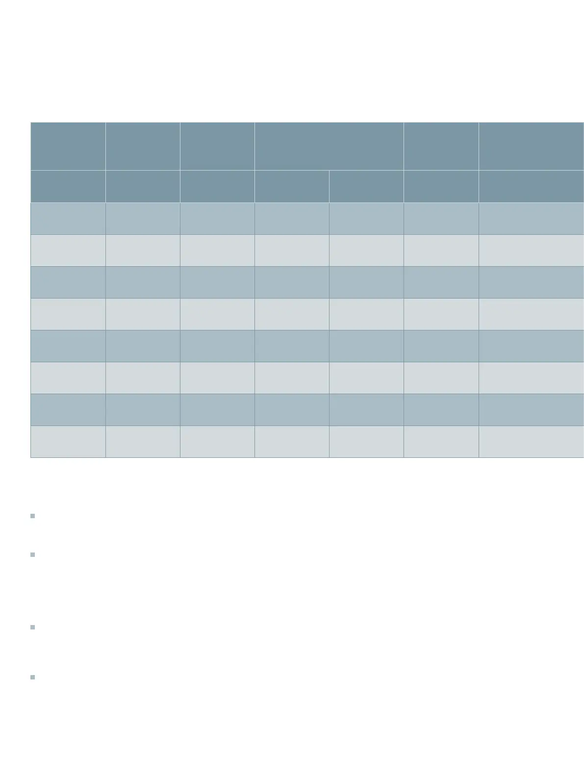
Table 13: Type GMSG vacuum circuit breaker ratings (new "constant kA" ratings basis)
These ratings are in accordance with:
ANSI/IEEE C37.04-1999 Standard Rating
Structure for AC High-Voltage Circuit
Breakers
ANSI/IEEE C37.06-2009 AC High-
Voltage Circuit Breakers Rated on a
Symmetrical Current Basis - Preferred
Ratings and Related Required
Capabilities for Voltages Above 1,000
Volts
ANSI/IEEE C37.09-1999 Standard Test
Procedure for AC High-Voltage Circuit
Breakers Rated on a Symmetrical
Current Basis
ANSI/IEEE C37.010-1999 Application
Guide for AC High-Voltage Circuit
Breakers Rated on a Symmetrical
Current Basis.
Footnotes:
1.
“xxxx” in type designation refers to the
continuous current rating 1,200 A, 2,000 A
or 3,000 A, as appropriate. The 4,000 A fan-
cooled rating is achieved using a 3,000 A circuit
breaker, in combination with fan cooling as
indicated in Footnote 4.
2.
Maximum design voltage for which the circuit
breaker is designed and the upper limit for
operation.
3.
K is listed for information purposes only. For
circuit breakers rated on a "constant kA" ratings
basis, the voltage range factor is 1.0.
4.
4000FC indicates that fan cooling is included in
the switchgear structure for this rating. 4000 A
rating is not available in outdoor equipment.
5.
All values apply to polyphase and line-to-line
faults.
6.
Standard duty cycle is O - 0.3s - CO - 3 min. - CO.
7.
Standard rating interrupting time is five-cycles
(83 ms). Optional rated interrupting time of
three-cycles (50 ms) is available (except with
24 Vdc tripping).
64
 Loading...