7/11
Siemens Building Technologies CC1N7418en
HVAC Products 08.04.2004
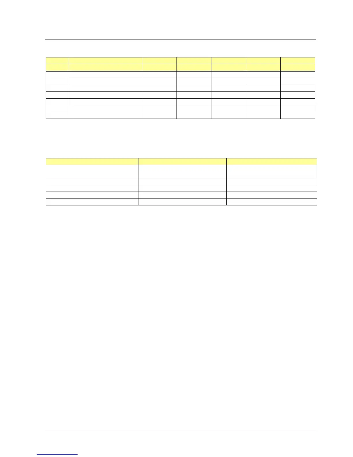
Function
(times in seconds)
1
)
AC 220...240 V LGA41.153A27 LGA41.173A27 LGA52.150B27 LGA52.171B27 LGA63.191A27
AC 100...110 V --- --- LGA52.150B17 --- ---
t1 Prepurge time --- --- approx. 13 approx. 13 approx. 13
t3 Preignition time 15 15 --- --- ---
t3´ Preignition time from start of «TSA» --- --- max. 5 4.5...7.5 max. 10
TSA Ignition safety time 5 10 5 4.5...7.5 10
TSAmax. Max. ignition safety time 10 20 10 20 20
t3n Postignition time max. 2 max. 2 --- --- ---
t4 Interval «BV1 – BV2» approx. 18 approx. 13 approx. 18 approx. 13 approx. 23
¹) All times specified apply to AC 220 V and AC 110 V respectively
For AC 240 V operation, above times are to be multiplied by 0.7
Fault Response of LGA41... Response of LGA52... / LGA63...
Erroneous flame signal during «t1»
or «t3»
Lockout ²) prior to the release of gas Lockout ²) prior to ignition and the re-
lease of gas
No flame on completion of «TSA» Lockout ²) Lockout ²)
Loss of flame during operation Repetition Repetition
No air pressure signal during «t1» --- No start
Air pressure failure during operation --- Shutdown
²)
After lockout, the burner control can be reset after about 60...90 seconds
The conductivity and rectifying effect of hot flame gases are used for flame supervision.
For that purpose, AC voltage is applied to the ionization probe which projects into the
flame.
The current that flows in the presence of a flame (ionization current) generates the
flame signal which is then fed to the input of the flame signal amplifier.
The amplifier is designed such that it only responds to the DC current component of the
flame signal, thus ensuring that a short-circuit between ionization probe and ground
cannot simulate a flame signal (since in that case, AC current would flow).
Control sequence
Control sequence in the
event of fault
Flame supervision with
ionization probe
 Loading...