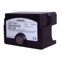
Do you have a question about the Siemens LMG21.350A27 and is the answer not in the manual?
Describes the application and intended use of the LMG2... burner controls for various burner types.
Highlights application-specific features and lists available LMG2... burner control versions.
Provides essential warnings to prevent personal injury, property damage, or environmental harm.
Covers engineering, mounting, and detailed installation notes for safe and correct operation.
Illustrates a connection diagram example for understanding wiring configurations.
Explains the requirements for loss-free signal transmission from ionization and UV detectors.
Details the mechanical construction of the burner control and its plug-in base.
Summarizes different burner control types with their parameters for selection.
Lists components for ordering, including burner controls, detectors, bases, and adapters.
Provides detailed technical specifications, environmental conditions, and terminal ratings.
Explains flame supervision using detector electrodes and measuring principles.
Illustrates the measuring circuit for detector currents with relevant components.
Details flame supervision with UV detectors and the ancillary unit AGQ2...A27.
Shows connection and measurement circuits for UV detectors and ancillary units.
Outlines prerequisites for startup, operational states, and undervoltage handling.
Explains control program behavior during faults and how to reset the unit.
Provides wiring diagrams and application examples for LMG21 and LMG25 burner controls.
Provides wiring diagrams and application examples for LMG22 burner controls.
Illustrates other application examples, such as burners without fan assistance.
Defines abbreviations and symbols used in the connection diagrams.
Explains the operating concept, LED indicators, and fault diagnosis steps.
Lists blink codes and their corresponding potential causes for fault identification.
Details how to measure and read the flame establishment time using blink codes.
Presents the internal schematic diagram for LMG21 and LMG25 burner controls.
Presents the internal schematic diagram for LMG22 burner controls.
Provides detailed physical dimensions for the burner control unit and plug-in base.
Shows the dimensions for the ancillary unit AGQ2...A27.
| Brand | Siemens |
|---|---|
| Model | LMG21.350A27 |
| Category | Controller |
| Language | English |


 Loading...