Do you have a question about the Siemens LMO44.255C2 and is the answer not in the manual?
Describes the intended application of the burner controls for startup and supervision.
Lists key characteristics and functionalities of the burner controls for oil burners.
General precautions to avoid injury, property damage, or environmental harm during operation.
Guidelines for mounting, electrical installation, and compliance with regulations.
Best practices for connecting flame detectors for reliable signal transmission.
Procedures for verifying safe operation during commissioning and maintenance.
Details of conformity to EEC directives and ISO standards.
Discusses the designed lifetime and replacement criteria for burner controls.
Instructions for proper disposal of the unit and its electronic components.
Describes the housing material, construction, and internal components.
Overview of different burner control types and their technical parameters.
Information on ordering burner controls and related accessories.
Details on ordering flame detectors, interfaces, and PC software.
Information on test adapters, demo cases, and lockout reset button extensions.
Provides electrical and physical specifications for the burner controls.
Specifies storage, transport, and operation conditions including temperature and humidity.
Details detector current requirements and permissible limits for flame supervision.
Explains the meaning of green LED indications for operational status.
Illustrates the measuring circuit for detector current using a microammeter.
Lists the conditions that must be met before the burner control can start.
Describes behavior during undervoltage and supervision of oil preheater.
Details the response to faults like mains failure or loss of flame.
Explains the maximum number of repetitions allowed before lockout.
Explains the lockout reset button and the multicolor signal lamp (LED).
Outlines visual and interface diagnostics for operational status and faults.
Details the color code table for the multicolor signal lamp during operation.
Describes how to activate visual diagnostics using the lockout reset button.
Lists red blink codes for the signal lamp and their corresponding possible causes.
Illustrates internal and external connection diagrams for LMO14, LMO24, and LMO44.
Details the operational control sequences for different LMO models.
Defines abbreviations and symbols used in the diagrams and text.
Explains the meaning of codes and symbols used in control sequence diagrams.
Provides dimensional drawings for the LMO burner controls.
Details the lengths available for the lockout reset button extension.
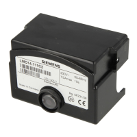
The Siemens LMO14..., LMO24..., and LMO44... series are microcontroller-based oil burner controls designed for the startup, supervision, and control of forced draft oil burners operating in intermittent mode. These controls are suitable for standard versions with an oil throughput up to 30 kg/h, with special versions available for throughputs exceeding 30 kg/h. These devices are primarily intended for use by Original Equipment Manufacturers (OEMs) who integrate burner controls into their products.
The LMO... series controls are engineered to manage the ignition and operation of 1- or 2-stage forced draft oil burners. They supervise yellow-burning flames using photo resistive detectors (QRB...) and blue-burning flames with blue-flame detectors (QRC...). The control sequence is precise and reproducible due to digital signal handling. Key functions include undervoltage detection, electrical remote reset, and a bridging contact for oil preheaters, along with monitoring the preheater's time. The LMO... series ensures controlled intermittent operation after 24 hours of continuous running and limits the number of repetitions to prevent excessive wear. In the event of a fault, the device provides multicolor indication of the fault status and operational messages.
| Brand | Siemens |
|---|---|
| Model | LMO44.255C2 |
| Category | Control Unit |
| Language | English |


 Loading...