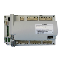
Do you have a question about the Siemens LMV3 series and is the answer not in the manual?
The LMV3 Burner / Boiler Management System is ideal for steam boilers, hot water boilers, thermal fluid heaters, and industrial burners.
Details components needed to build an LMV3 system, including base units, displays, and cables.
Provides instructions and dimensions for mounting the LMV3 controller unit.
Crucial safety guidelines for operating, maintaining, and modifying the LMV3 system.
Lists the standards and approvals the LMV3 system has obtained.
Introduces wiring concepts for the LMV3, covering terminals and common applications.
Explains the two types of grounds: Protective Earth (PE) and Reference Ground (GND).
Details the terminal layout and functions for the LMV3 controller.
Details the terminal layout and functions for the AGM60 dual fuel module.
Provides various wiring diagrams for LMV3 system components and configurations.
Explains the parameter structure, access levels, and grouping of LMV3 parameters.
Illustrates input/output terminal status across various burner sequence phases.
Essential checks and conditions required before commissioning the LMV3 system.
Specific prerequisites for commissioning LMV3 systems equipped with Variable Speed Drives.
Guideline for setting up LMV3 parameters from a default set for initial operation.
Procedure for setting actuator direction of rotation and reference points.
Steps for copying parameter sets between LMV3 units using the AZL display.
Step-by-step guide for the initial light-off and tuning of the LMV3 system.
Procedure for setting up fuel-to-air ratio curves for optimal burner performance.
Provides extra advice and considerations for a successful commissioning process.
Explains the use of Variable Speed Drive (VSD) for combustion air blower control.
Covers basic principles of Variable Frequency Drives and AC induction motors.
Discusses the use and recommendations for line reactors with VFDs.
Details output wiring practices and the use of load reactors for VFDs.
Explains shaft current issues and the role of braking resistors with VFDs.
Covers VFD types (Vector, Volt/Hz) and general configuration guidelines.
Details the use and characteristics of brushless DC (PWM) blowers with the LMV3.
Explains basic operating principles of centrifugal blowers relevant to LMV3 control.
Procedure for standardizing the LMV3 to accurately read blower speed.
Defines tolerance bands for monitoring blower speed during operation.
Describes how blower speed is managed and responds during acceleration and deceleration.
Procedure for setting up VSD control in a parallel positioning application.
Steps for configuring and using VSD speed shift for fuel-to-air ratio trimming.
Additional tips for optimizing VSD speed shift implementation.
General advice and best practices for VSD control in burner applications.
Introduction to troubleshooting the LMV3, explaining fault codes and history.
Detailed list of error codes, meanings, and corrective actions for LMV3 system faults.
Covers Modbus connection, master-slave principle, and data transmission.
Explains CRC16 checksum for error detection and handling erroneous Modbus accesses.
Details the timing and sequence of Modbus data inquiries and responses.
Covers communication timing, slave handling, response time, and message limits.
Lists supported Modbus functions and the address map for LMV3 parameters.
Cross-references Modbus addresses for LMV3 inputs to their designations.
Cross-references Modbus addresses for LMV3 outputs to their designations.
Cross-references Modbus addresses to LMV3 parameters for various functions.
Defines data formats, access types, and ranges used in Modbus communication.
Covers handling of Modbus communication timeouts and preselected outputs.
Discusses Modbus interaction with ACS410/AZL2 and error handling procedures.
Introduction to the ACS410 software, its capabilities, and system requirements.
Step-by-step guide for installing the ACS410 software and drivers on a PC.
Procedure for establishing communication between the LMV3 and a PC via interface module.
Procedure for backing up LMV3 parameter sets to a PC using ACS410 software.
Procedure for restoring parameter sets from a PC to an LMV3 using ACS410 software.
Steps for generating, saving, and printing a comprehensive LMV3 startup report.
Procedure for saving and viewing system behavior trends using ACS410 software.
Guide to viewing the LMV3 inputs, outputs, and operating state via ACS410 status screen.
Overview of the LMV3 Application Guide, covering programming, wiring, and operation examples.
Details wiring, operation, and notes for integrating a fresh air damper with the LMV3.
Procedure for setting up hot standby on a steam boiler using LMV3 and RWF55 controller.
Introduction to using RWF55 for low fire hold to prevent boiler thermal shock.
Procedure for implementing low fire hold on a steam boiler with RWF55 analog output.
Procedure for implementing low fire hold on a hot water boiler with RWF55 analog output.
Procedure for implementing low fire hold on a steam boiler with RWF55 3-position output (LMV37).
Procedure for implementing low fire hold on a hot water boiler with RWF55 3-position output (LMV37).
Explains the operation and provides an example for low fire hold with RWF55.
Introduction and procedure for performing pilot valve leakage tests.
Details Option 1 for pilot valve proving on startup with SKP25s.
Details Option 2 for pilot valve proving with SKP25 on main gas train, solenoids on pilot.
Details Option 3 for pilot valve proving on startup and main valve proving on shutdown.
Introduction and procedure for purge proving using pressure switches or damper end switches.
Explains the operation of the purge proving sequence with the LMV3.
Introduction and procedure for the LMV37's revert to pilot feature.
Details the sequence of operation for the LMV37's revert to pilot function.
Provides an example of critical RWF55 settings for the revert to pilot operation.
Key considerations and notes regarding the LMV37's revert to pilot function.
Details wiring, operation, and notes for integrating a stack damper with the LMV3.
Explains the operation and important notes for the stack damper system.
| Brand | Siemens |
|---|---|
| Model | LMV3 series |
| Category | Control Unit |
| Language | English |


