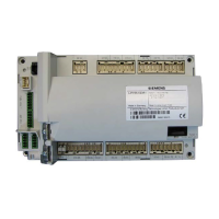
Do you have a question about the Siemens LMV37.420A1 and is the answer not in the manual?
Observing warning notes to prevent injury, property damage, or environmental harm.
Specifications for mains voltage, frequency, power, safety class, and protection degree.
Details on input/output terminal loading, including fuses, voltage, current, and contact recommendations.
Discusses flame display conditions, detector types, and selection parameters.
Details loss of flame, extraneous light, no flame, flame intensity, and detector supervision.
Explains the safety loop input (X3-04) and burner flange contact (X3-03) as part of safety functions.
Covers external controller inputs, air pressure switch, and valve proving inputs.
Details min/max gas/oil pressure inputs, start release, and reset functionality.
Details valve proving for gas, including with separate pressure switch or min-gas switch.
Details connecting to load controllers via contacts (X5-03) for modulating and multistage operation.
Details modulating operation, curve definition using 10 curvepoints, and parameter settings.
Guides on setting curvepoints P0 and P9 for various modulating modes, including warm and cold settings.
Details the referencing process for actuators after power-on and during shutdown to ensure accuracy.
Provides proposals for implementation to detect and prevent actuator mix-ups.
Describes acquiring fan speed via proximity switches or Hall generators and standardizing speed.
Explains fan speed control to setpoint and supervision for safety shutdown if setpoints are not met.
Guides on parameterizing the VSD, standardizing speed, and checking air-fuel ratio control settings.
Details communication with BAC systems via COM X92, including Modbus and handling communication breakdowns.
Describes ACS410 software functions for system visualization, configuration, and data backup/recovery.
Explains the error history storing the last 25 errors and classification based on severity.
Describes the AZL2 unit's display elements, symbols, and the function of each button.
Covers manual lockout and manual control of burner output via the AZL2 unit.
Details the process of creating and restoring backup data sets for unit settings.
Describes normal, standby, and startup/shutdown displays, including program phases and remaining time.
Explains the displays for operating positions like 'oP', 'P0', 'P1', 'P2', 'P3' in different modes.
Covers displaying fault status, errors, and info, including lockout and safety shutdown messages.
Explains accessing the parameter level, requiring a password, and the OEM's responsibility.
Guides on entering passwords for heating engineer and OEM, and changing existing ones.
Guides on accessing and modifying parameters with direct display using examples like 'Program Stop'.
| Brand | Siemens |
|---|---|
| Model | LMV37.420A1 |
| Category | Control Unit |
| Language | English |


 Loading...