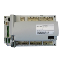
Do you have a question about the Siemens LMV36.520A1 and is the answer not in the manual?
General warnings and safety precautions for installation and operation.
Instructions and specifications for mounting the LMV36 and AGM60 units.
Guidelines for correct installation, including wiring and cable management.
Details on electrical connections for LMV36 and AGM60, including voltage categories.
Important checks and documentation required during system commissioning.
Guidelines for adjusting electronic fuel-air ratio control and parameter settings.
Information on designed lifetime, service notes, and proper disposal of the unit.
Description of the LMV36 as a microprocessor-based burner management system.
Description of the AGM60 switch unit for fuel changeover and feedback signals.
Explanation of the fuel selection process and changeover logic.
Detailed technical data for the LMV36 basic unit, including terminal loading.
Technical specifications for ionization, UV, and photoresistive flame detectors.
Technical data for the AGM60 switch unit, including environmental conditions.
Detailed physical dimensions of the LMV36 basic unit with illustrations.
Detailed physical dimensions of the AGM60 switch unit with illustrations.
Description of flame signal inputs and connection choices for various detectors.
Description of various digital inputs like safety loop, burner flange, and controller inputs.
Description of safety and non-safety related digital outputs for actuators and alarms.
Table of time parameters used to define fuel train characteristics and sequence timings.
Explanation and parameterization of gas valve proving for safety and leak detection.
Details on special functions like reset, manual lockout, and startup alarms.
Application example and sequence diagram for gas direct ignition modes.
Application examples and sequence diagrams for gas pilot ignition types.
Application examples and sequence diagrams for light oil direct ignition modes.
Description of actuator function, resolution, and angle definitions.
Procedures for actuator referencing and setting direction of rotation.
Methods for monitoring actuator positions and detecting errors.
Measures to prevent mix-ups between fuel and air actuators during installation.
Instructions for activating VSD or PWM fan control via operating modes.
Specifics on VSD control via voltage interface and PWM fan control.
Procedures for standardizing and supervising fan speed for optimal performance.
Voltage values and curvepoints for different output stages in operation modes.
Configuring fuel meters, pulse valency, and reading/resetting meter data.
Calculating and reading current fuel throughput based on meter pulses.
Connecting to BAC systems via COM X92 for data link and bus adaptation.
Configuring the basic unit as a slave for Modbus communication.
Overview of ACS410 software functions for visualization, configuration, and backup.
Details on the makeup of the error history and how to delete it.
Description of the AZL2 unit's display elements and button functions.
Procedures for manual lockout and manual control of burner output.
Steps for creating backups and restoring parameter sets using the AZL2 unit.
Description of the normal operating display and standby mode.
How program phases, remaining times, and operating positions are displayed.
Display of errors, faults with lockout, and activation of service modes.
Explanation of accessing different operation levels via button combinations.
Steps to display identification date, number, and startup counts in the info level.
Accessing and displaying service values like number of faults and flame intensity.
Procedure for entering OEM and heating engineer passwords.
Steps to enter the burner identification number character by character.
Instructions for changing heating engineer's and OEM's passwords.
Overview of the hierarchical structure of parameter levels and access.
Guide to setting parameters with direct display, using 'Program Stop' as an example.
Guide to setting parameters without direct display, using 'Operating Hours Resettable' as example.
Guide to setting parameters with index and direct display, using 'No-flame positions' as example.
Guide to setting parameters with index and no direct display, using 'Errors' as example.
Procedures for initial commissioning and setting fuel-air ratio curves.
| Brand | Siemens |
|---|---|
| Model | LMV36.520A1 |
| Category | Control Unit |
| Language | English |


 Loading...