32/248
Building Technologies Division Basic documentation LMV36... CC1P7544en
Infrastructure & Citiies Sector 4 Technical data 25.09.2013
4.4 Flame detectors
4.4.1 Ionization probe
For continuous operation!
No-load voltage at ION terminal
(X10–05 pin 2)
Approx. U
Mains
Caution!
Protect the ionization probe against electric shock hazard!
Short-circuit current Max. AC 1 mA
Required detector current Min. DC 4 µA, flame display approx. 30 %
Possible detector current Max. DC 16…40 µA, flame display
approx. 100 %
Max. perm. length of detector cable
(laid separately)
3 m (wire–ground 100 pF/m)
Warning!
Simultaneous operation of QRA... and ionization probe is not permitted!
Note
The higher the detector cable’s capacitance (cable length), the more voltage at the
ionization probe, and thus the detector current, drops. Long cable lengths plus very
highly resistive flames might necessitate low-capacitance detector cables (e.g. ignition
cable). In spite of technical measures taken in the circuitry aimed at compensating
potential adverse effects of the ignition spark on the ionization current, it must be
made certain that the minimum detector current required is already reached during
the ignition phase. If this is not the case, the connections on the primary side of the
ignition transformer must be changed and / or the electrodes relocated.
Threshold values when flame is supervised by an ionization probe:
- Start prevention (extraneous light) Intensity of flame (parameter 954) ≥18%
- Operation Intensity of flame (parameter 954) >24%
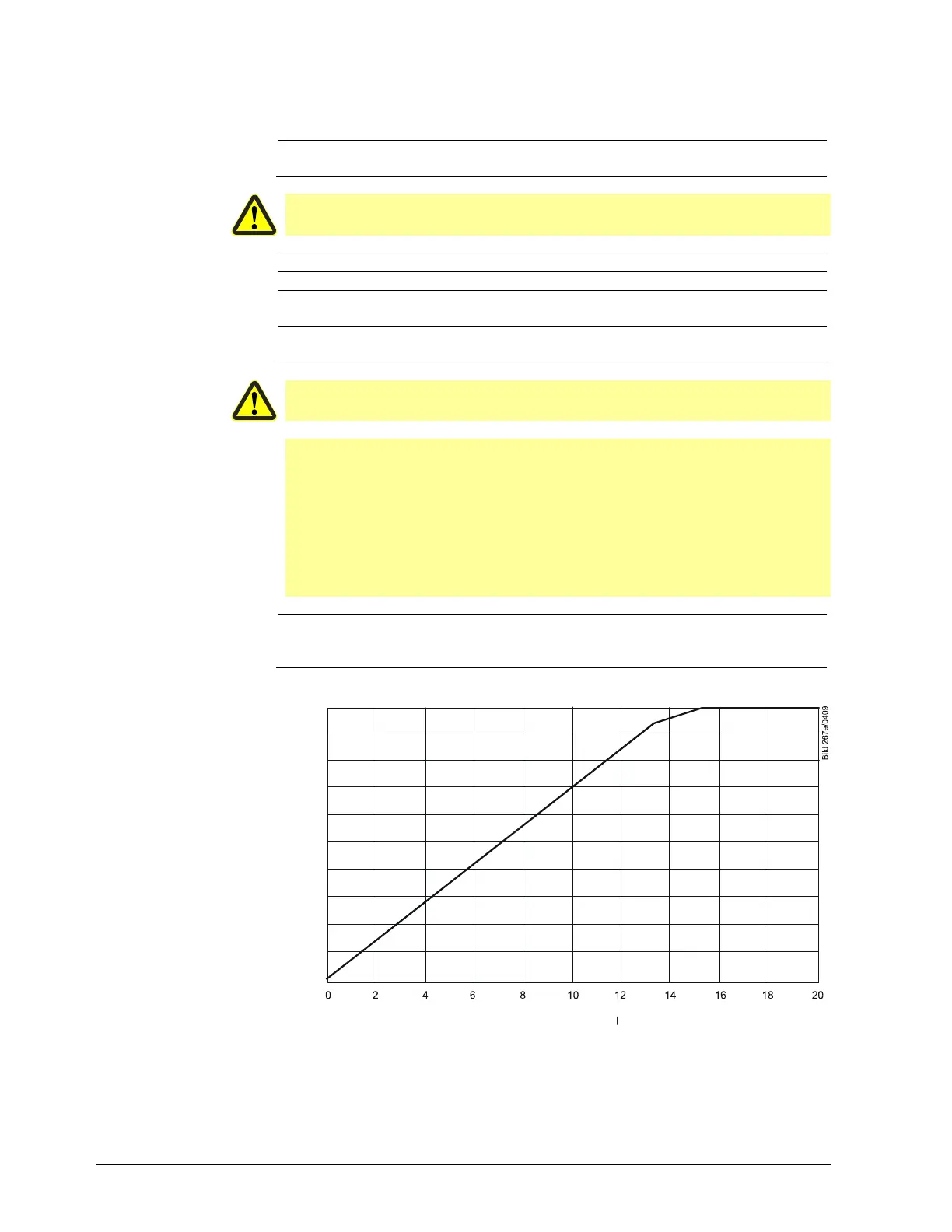
ION input
l
me i
te
sit
i
100
90
80
70
60
50
40
30
20
10
0
Ionization current in uA
Figure 10: Ionization input at AC 120 V

 Loading...

