76/248
Building Technologies Division Basic documentation LMV36... CC1P7544en
Infrastructure & Citiies Sector 7 Basic unit 25.09.2013
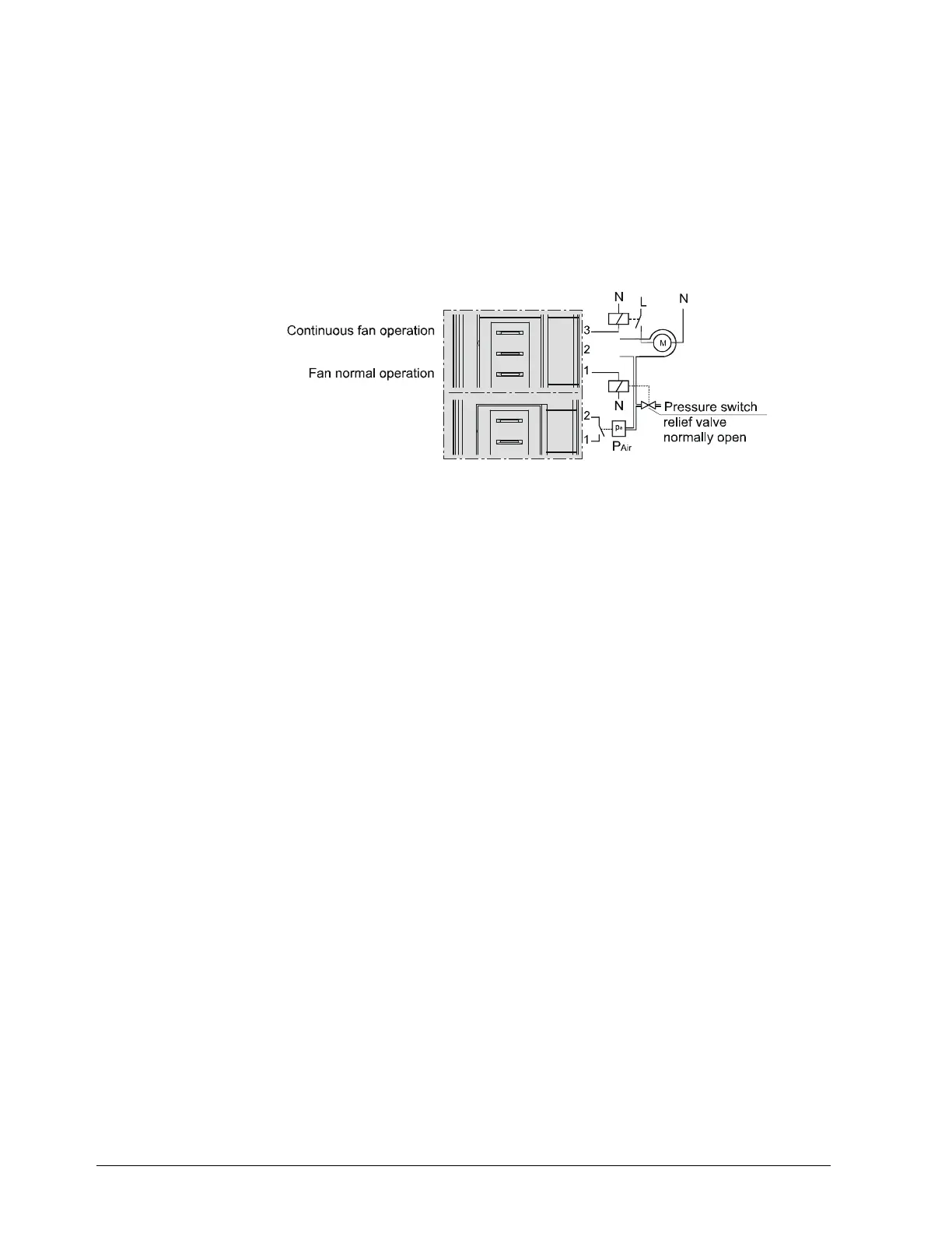
7.5.5.10. Continuous fan
With burners that can be damaged by heat (e.g. several burners using the same
combustion chamber), continuous purging may be required. In that case, the fan
operates continuously in all phases.
For that purpose, the fan motor contactor is to be connected to X3-05, pin 3, tapped
after the unit fuse and the safety loop.
For checking the air pressure switch, a pressure switch relief valve must be connected
to fan output X3-05, pin 1. When output X3-05, pin 1, is activated, the relief valve diverts
the fan pressure to the air pressure switch and, when deactivated, ensures that no
pressure is fed to the switch.
Example:
LMV...
Bild 296e/1010
X3-05
X3-02
Figure 42: Continuous fan

 Loading...

