Technical Instructions LMV Series
Document No. LV3-1000
Appendix A Page 18 SCC Inc.
Pilot Valve Proving (continued)
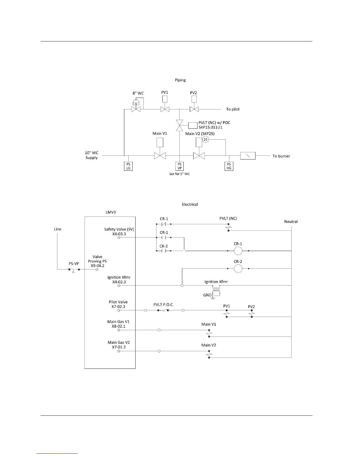
Option 2: On Startup, SKP25 on the Main Gas Train, Solenoid Valves on the Pilot Train
Figure 9: Option 2 Piping and Electrical Schematics

 Loading...


