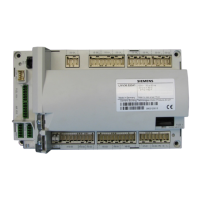
Technical Instructions LMV Series
Document No. LV3-1000
Section 4 Page 4 SCC Inc.
Pre-Requisites for LMV3 Systems with a VSD
1. All pre-requisites of the Basic LMV3 system apply.
2. For VFD equipped burners, the blower motor speed sensor and speed wheel must be installed
correctly.
3. Proper grounding between the LMV3, the VSD, and the motor must be installed. See Section 2
(Wiring) for more details.
4. For VFD equipped burners, VFD parameters must be set correctly to be compatible with both
the LMV3 and the blower motor. See Section 5 (VSD) for more details. Particular attention
should be paid to the following:
a. Analog signal configuration. Both the LMV3 and VFD must be configured for a 0-10 VDC
signal.
b. Ramp rates between the LMV3 and the VFD must be compatible. In general, ramp rates
of the VFD should be 10 seconds less than the LMV3.
c. VFD must be set up as a slave unit for a 0-10 VDC signal. Damping, dead band, and PID
functions must be disabled.
d. The frequency (Hz) output of the drive must be directly proportional to the analog input
signal.
e. Acceleration / deceleration curves must be linear instead of “S-shaped”.
f. Ramp settings must be ramp up / ramp down instead of ramp up / coast down.
g. Any type of damping or stall prevention in the VFD should be deactivated.
5. LMV3 / VSD combination must be “Standardized” before operation. See Section 5 (VSD) for
more details.
a. Verify that the air damper opens to pre-purge position before the blower is energized
for standardization.

 Loading...


