LMV Series Technical Instructions
Document No. LV3-1000
SCC Inc. Page 21 Section 4
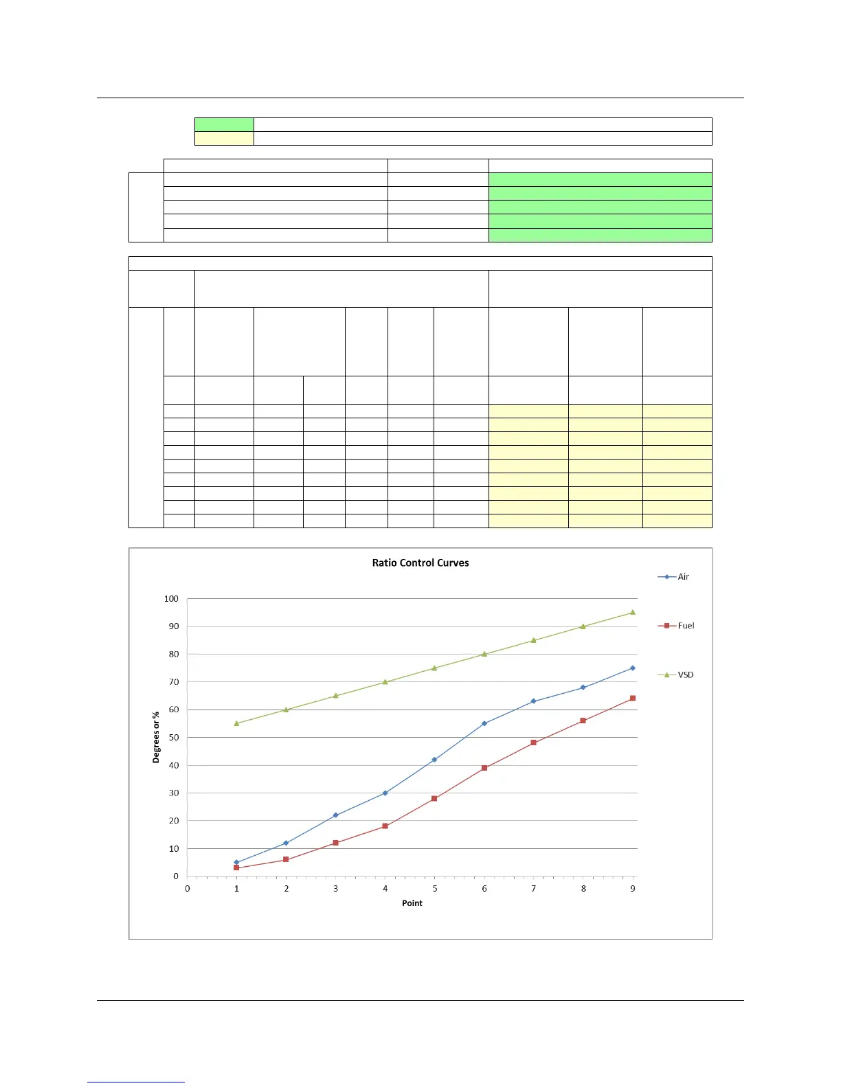
Figure 4-5: Example of LMVx Curves Spreadsheet
Burner Head (manifold) Pressure at High Fire
Burner Turndown
Heating Value of Gas
Boiler Efficiency
Gas Flow to
Burner
(Auto Calc)
Burner
Head
Pressure
(Approx)
Steam Flow
230
o
F Feed
100 PSIG
Steam
(Approx)
MW IN WC BHP lb/hr Deg Deg %
1 1600 1.60 0.47 0.2 39.2 1324.3 5.0 3.0 55.0
2 2400 2.40 0.70 0.5 58.8 1986.5 12.0 6.0 60.0
3 3200 3.20 0.94 1.0 78.4 2648.6 22.0 12.0 65.0
4 4000 4.00 1.17 1.5 98.0 3310.8 30.0 18.0 70.0
5 4800 4.80 1.41 2.2 117.6 3972.9 42.0 28.0 75.0
6 5600 5.60 1.64 2.9 137.2 4635.1 55.0 39.0 80.0
7 6400 6.40 1.87 3.8 156.8 5297.3 63.0 48.0 85.0
8 7200 7.20 2.11 4.9 176.4 5959.4 68.0 56.0 90.0
9 8000 8.00 2.34 6.0 196.0 6621.6 75.0 64.0 95.0
Manually Input during Ratio Control Curve Commissioning
Actuator / VSD Ratio Control Curves
These Cells are Calculated from the "Application Info" Cells Above
Burner Output at High Fire
Indicates information to be filled out before commissioning ratio control curves
Indicates information to be filled out during commissioning of ratio control curves
 Loading...


